Intelligent helmet and manufacturing method thereof

A technology of smart helmets and manufacturing methods, applied in the direction of helmets, helmet caps, hat products, etc., to achieve the effects of reducing product weight, avoiding detachment, and reducing manufacturing costs

Pending Publication Date: 2016-12-14
GUANGDONG COROS SPORTS TECH JOINT CO
View PDF5 Cites 8 Cited by
  • Summary
  • Abstract
  • Description
  • Claims
  • Application Information

AI Technical Summary

Problems solved by technology

[0004] The purpose of the present invention is to provide a smart helmet and its manufacturing method, in which the smart components and the helmet shell are integrally formed to solve the above-mentioned problems existing in the production of the existing smart helmet

Method used


Image

  • Intelligent helmet and manufacturing method thereof
  • Intelligent helmet and manufacturing method thereof
  • Intelligent helmet and manufacturing method thereof

Examples


Embodiment 1

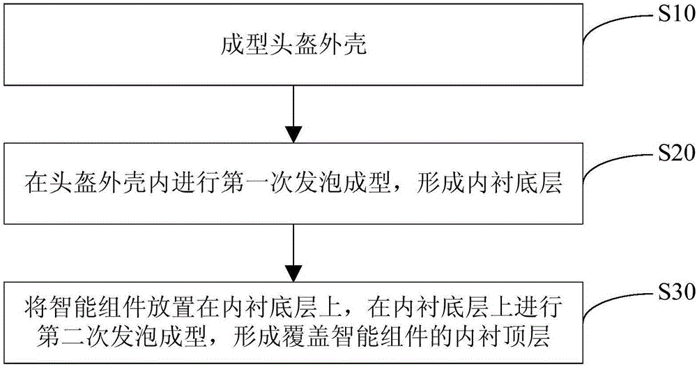
[0038] This embodiment provides a method for manufacturing a smart helmet, specifically as figure 1 As shown, the manufacturing method includes the following steps:

[0039] S10: Molded helmet shell.

[0040] That is, the PC sheet is molded into the helmet shell of the required shape by blistering, and the required helmet shell can also be selected by injection molding according to the needs. The specific methods of blistering or injection molding are all prior art, and the processing technology thereof will not be described in this embodiment.

[0041] S20: Carry out the first foam molding in the helmet shell to form the inner substrate layer.

[0042] Specifically, the helmet shell is put into a foaming mold adapted to its shape, and then foamed in the foaming mold to form an inner substrate layer located in the helmet shell. In this embodiment, the in-mold steam pressure of the above-mentioned foam molding is 0.8-1.5 standard atmospheric pressure, and the in-mold steam t...

Embodiment 2

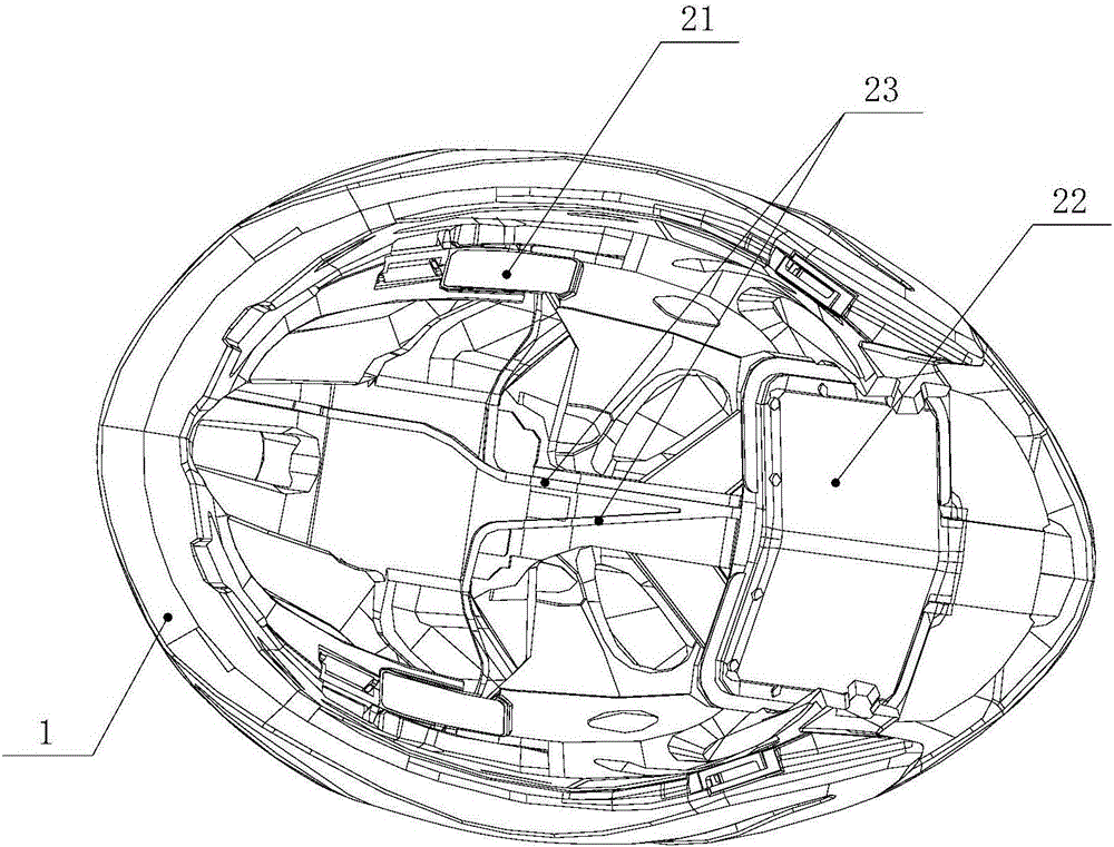
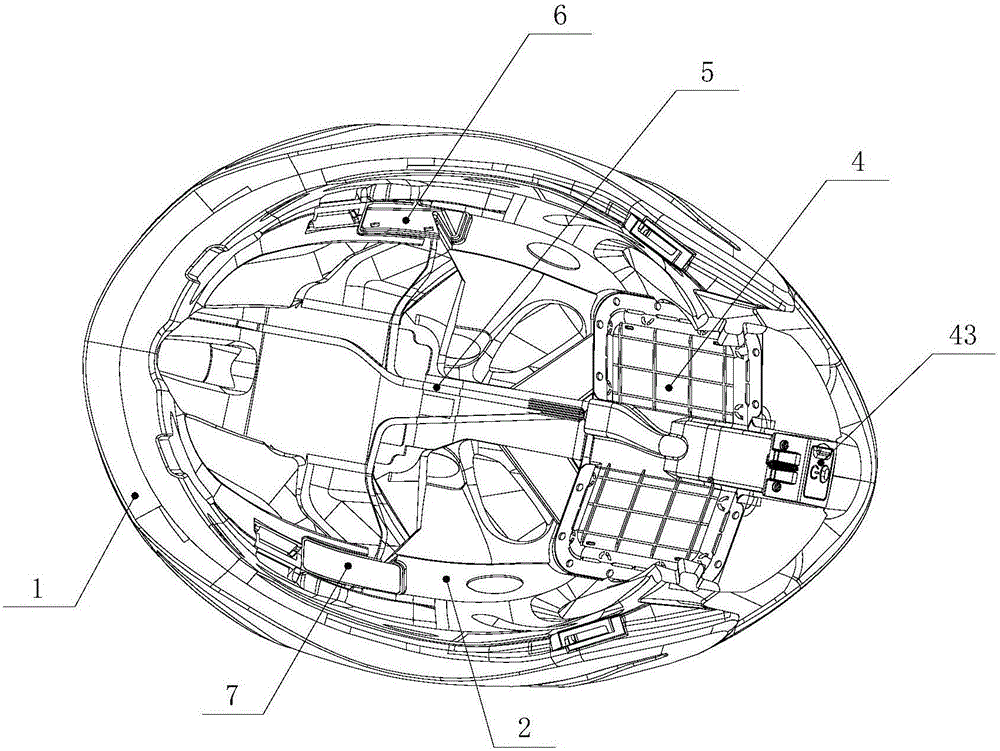
[0063] This embodiment provides a smart helmet, which is manufactured using the manufacturing method described in Embodiment 1, specifically, as Figure 2-4 As shown, it includes a helmet shell 1, an inner substrate layer 2 and an inner lining top layer 3 that are formed in the helmet outer shell 1 and arranged in sequence from the inside to the outside through foam molding, and the inner substrate layer 2 and the inner lining top layer 3 are integrally formed There are smart components. By integrally molding the smart components with the inner base layer 2 and the inner liner top layer 3, the user's comfort when using the smart helmet can be improved, and the use of the wire frame is eliminated, thereby reducing the manufacturing cost. In this embodiment, the inner substrate layer 2 and the inner lining top layer 3 are respectively molded through two times of foam molding. The specific molding process can refer to the manufacturing method of the smart helmet described in the ...


PUM


Abstract

The invention belongs to the technical field of production of helmets and discloses an intelligent helmet and a manufacturing method thereof. The manufacturing method of the intelligent helmet comprises the following steps: step 1: molding a helmet shell; step 2: carrying out first time of foaming and molding in the helmet shell to form a lining bottom layer; and step 3: putting an intelligent assembly on the lining bottom layer and carrying out second time of foaming and molding on the lining bottom layer to form a lining top player covering the intelligent assembly. The intelligent helmet comprises the helmet shell, and the lining bottom layer and the lining top player which are molded in the helmet shell and are arranged in sequence from inside to outside; and the intelligent assembly is integrally molded between the lining bottom layer and the lining top player. When the intelligent helmet disclosed by the invention is produced through the manufacturing method above, the intelligent assembly and the helmet shell are integrally foamed and molded; and compared with an existing technology of mounting the intelligent assembly through a lead wire framework, manufacturing and a mold of the lead wire framework are eliminated; and the weight of a product lightened and the manufacturing cost is effectively reduced.

Description

technical field [0001] The invention relates to the technical field of helmet production, in particular to an intelligent helmet and a manufacturing method thereof. Background technique [0002] In the production of existing smart helmets, the helmet shell and the smart components are usually manufactured separately. First, the helmet shell and its inner lining are molded, and then the manufactured smart components are installed in the helmet shell through the wire skeleton, so as to Completed the production of rectified smart helmets. [0003] In the above-mentioned production process, it is necessary to add additional lead frame to realize the installation of the smart component, which increases the manufacturing steps of the lead frame and the mold for manufacturing the lead frame, and the manufacturing cost is relatively high. Moreover, the use of the above-mentioned wire frame needs to be fixed with the helmet shell by a fixing piece. When the user uses it, there may b...

Claims


Application Information

Patent Timeline
Patent Type & Authority Applications(China)
IPC IPC(8): A42B3/04
CPCA42B3/0406
Inventor 戎海峰钟鑫熊裕辉周小波潘擒虎
Owner GUANGDONG COROS SPORTS TECH JOINT CO
Why Eureka
Try Eureka