
Indoor positioning method based on UWB technology

An indoor positioning and technology technology, applied in electrical components, synchronization devices, wireless communication and other directions, can solve the problems of reducing communication efficiency, affecting positioning accuracy, affecting data reception, etc., to improve throughput, realize label capacity, and avoid data reception. Effect

Inactive Publication Date: 2016-12-07
BEIJING YONGANXINTONG TECH CO LTD
View PDF3 Cites 27 Cited by
  • Summary
  • Abstract
  • Description
  • Claims
  • Application Information

AI Technical Summary

Problems solved by technology

[0013] It can be seen from the above formula that when the total time occupied by the signals transmitted by all tags in the air transmission is less than 0.184 or 18.4% (with 1 second as the column, the total communication time is only 0.184 seconds), the probability of successful data transmission of the tag data in the air will be It is greatly improved, according to statistics, it is about 97%, but the communication efficiency of 18.4% is very low. When there are few tags in the reader's recognition range, it can work very well. When there are many tags in the reader's recognition range, the air transmission occupies When the total time exceeds 18.4%, the probability of signal collision will be greatly increased, and the communication efficiency will be greatly reduced
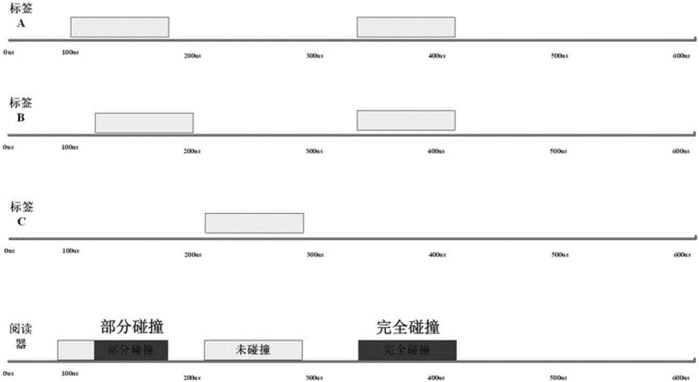
[0014] Traditional active RFID tags, based on the consideration of power consumption and service life, often use a simple pure ALOHA method, that is, the tag sends data information to the reader at random intervals, but for the application of UWB technology, in the process of sending data from the tag , if other tags are also sending data, the signals received by the reader may collide partially or completely, such as image 3 shown
Since UWB technology requires high-precision positioning of tags, if there are many tags, the probability of collision is high, which will not only affect data reception, but also affect positioning accuracy

Method used


Image

  • Indoor positioning method based on UWB technology
  • Indoor positioning method based on UWB technology
  • Indoor positioning method based on UWB technology

Examples


Embodiment Construction

[0043] In order to make the technical problems, technical solutions and advantages to be solved by the present invention clearer, a detailed description will be given below in conjunction with the accompanying drawings and specific embodiments.

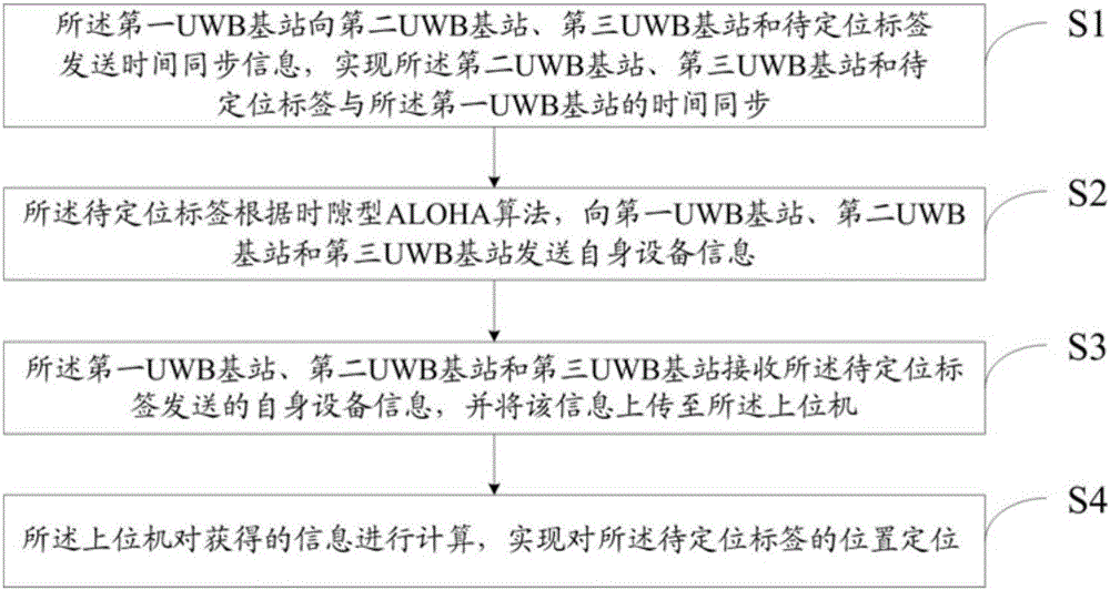
[0044] On the one hand, the present invention provides an indoor positioning method based on UWB technology, which is used in a wireless positioning system. The wireless positioning system includes a host computer and a first UWB base station, a second UWB base station, and a third UWB that can communicate with the host computer wirelessly. Base station, and several tags to be located that can communicate wirelessly with the first UWB base station, the second UWB base station, and the third UWB base station using the slotted S-ALOHA algorithm, such as figure 1 As shown, the methods include:

[0045] S1: The first UWB base station sends time synchronization information to the second UWB base station, the third UWB base station, and the tag ...


PUM


Abstract

The invention discloses an indoor positioning method based on UWB technology, and belongs to the field of high-precision indoor positioning. The method comprises the steps that a first UWB base station sends time synchronization information to a second UWB base station, a third UWB base station and a to-be-positioned label to realize the time synchronization of the equipment; the to-be-positioned label sends own equipment information to the first UWB base station, the second UWB base station and the third UWB base station according to a time slot ALOHA algorithm; the first UWB base station, the second UWB base station and the third UWB base station receive the own equipment information sent by the to-be-positioned label and upload the information to an upper computer; and the upper computer calculates the acquired information to position the to-be-positioned label. Compared with the prior art, the indoor positioning method disclosed by the invention has the advantages of low cost, small signal collision probability, no influence on data reception, high positioning accuracy and capability of expanding the label capacity.

Description

Technical field [0001] The invention relates to the field of high-precision indoor positioning, in particular to an indoor positioning method based on UWB technology. Background technique [0002] In wireless communication technology, the problem of communication collision has been a long-standing problem. For UWB indoor positioning technology, to achieve reliable positioning of a large number of tags, it is necessary to realize the anti-collision of tags. The current anti-collision in wireless communication There are mainly the following methods for processing: [0003] Existing technology one [0004] Frequency division multiplexing: A technology that simultaneously provides several transmission channels using different carrier frequencies for communication users. A tag reader contains receiving channels of multiple frequency bands, and each channel will not be affected by other receiving channels. The responding tags are also artificially allocated a fixed channel. The tags of m...

Claims


Application Information

Patent Timeline
IPC IPC(8): H04W56/00H04W64/00H04W74/08
CPCH04W56/0015H04W64/006H04W74/0833
Inventor 刘佳
Owner BEIJING YONGANXINTONG TECH CO LTD
Learn More