
Outdoor face recognition method and system

A facial recognition system and image technology, applied in the field of biometric recognition, can solve the problems of low signal-to-noise ratio, low accuracy, and inability to accurately locate the snapshot position of the face, so as to improve the signal-to-noise ratio and improve the accuracy.

Inactive Publication Date: 2016-12-07
CHENGDU BESTVISION TECH
View PDF13 Cites 21 Cited by
  • Summary
  • Abstract
  • Description
  • Claims
  • Application Information

AI Technical Summary

Problems solved by technology

However, when used under strong outdoor light, since the sun contains near-infrared components, the signal-to-noise ratio of the imaging is very low, and the facial imaging will have great changes at different incident angles of the sun, making most of the classic facial recognition algorithms in the prior art (such as PCA, LDA, LPP, etc.) the accuracy rate will be very low, or even completely invalid
[0005] Second, the existing facial recognition device cannot accurately locate the capture position of the face. In order to obtain a facial image that meets the recognition requirements, it is necessary to continuously adjust the position between the head and the camera, which prolongs the time for facial recognition capture and recognition of the face. The user's work efficiency greatly affects the user's good experience
[0006] Third, when the face recognition device is not performing face recognition tasks, the infrared fill light is always in working condition, which greatly shortens the service life and fill light quality of the fill light, and also increases the power consumption of the face recognition device

Method used


Image

  • Outdoor face recognition method and system
  • Outdoor face recognition method and system
  • Outdoor face recognition method and system

Examples


no. 1 approach

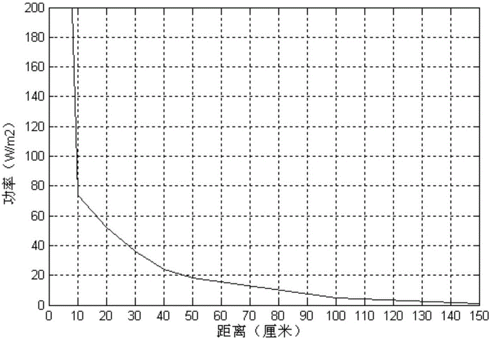
[0080] figure 1 It is a data statistical chart of the variation of the supplementary light intensity of the supplementary light measured by the inventor in the process of implementing the present invention with distance.

[0081] It should be noted that in the experiment, the inventor selected an infrared lamp with a power of 36W and a supplementary light band of 940nm as the supplementary light. of optical power. The purpose of adding an optical filter is to ensure that the optical power measured by the infrared optical power meter is the specified band.

[0082] like figure 1 As shown, the ordinate indicates the optical power of the supplementary light board measured by the infrared optical power meter, and the abscissa indicates the distance between the infrared optical power meter and the supplementary light board. from figure 1 It can be seen from the figure that the optical power measured at a distance of 10 cm from the fill light board is more than 10 times that mea...

Embodiment approach

[0086] A supplementary light is used to supplement light to the predetermined area, and the luminous intensity of the supplementary light is greater than a predetermined threshold. The supplementary light in the embodiment of the present invention is arranged on the supplementary light board, and the luminous intensity of the supplementary light is greater than a predetermined threshold when the infrared light power meter is used to measure the supplementary light, measured by the supplementary light per square meter Optical power not less than 30 watts. The supplementary light can use an infrared lamp with a wavelength between 850mm-940mm, and the number of supplementary light can be changed according to the power of the supplementary light. It should be noted that, the more the number of supplementary lights, the greater the power of each supplementary light, the greater the luminous intensity of the entire supplementary light panel, and thus the higher the signal-to-noise r...

no. 2 approach

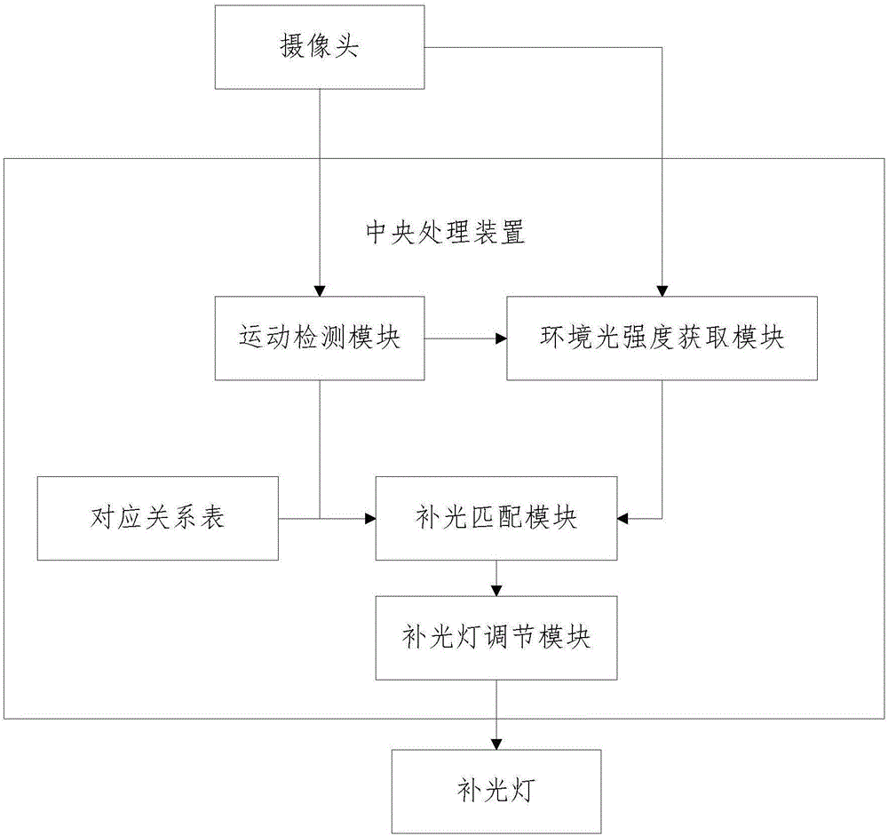
[0090] figure 2 It is a schematic diagram of the module relationship of the outdoor facial recognition system in the second embodiment of the present invention.

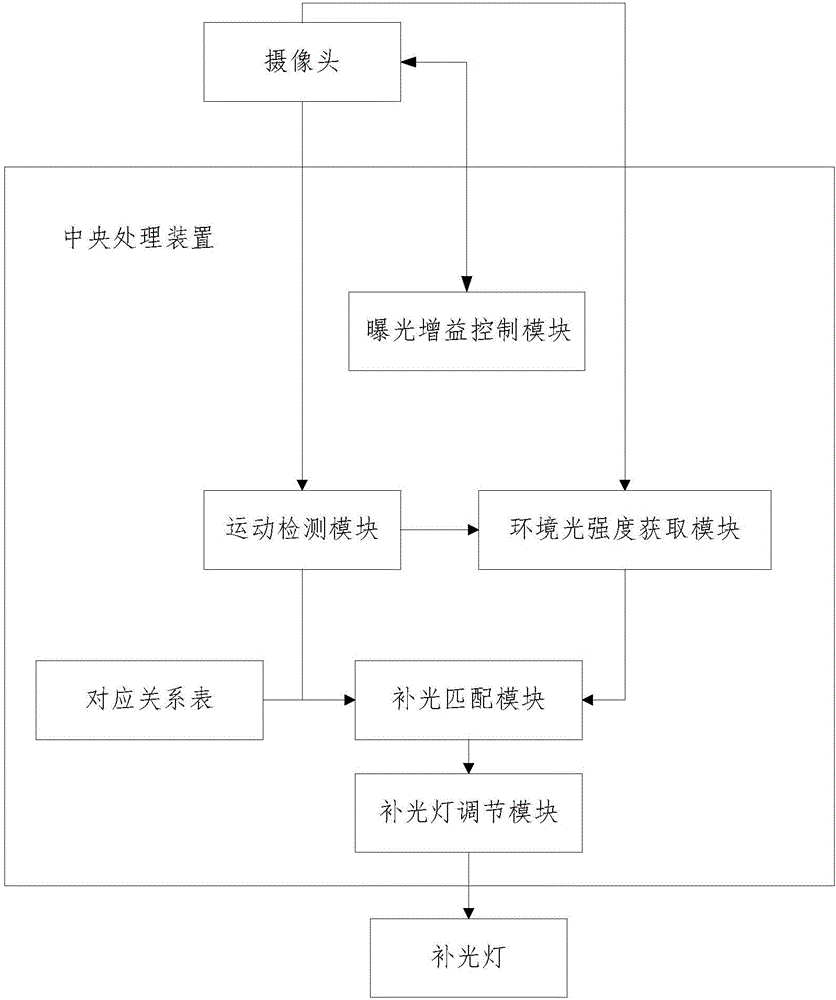
[0091] like figure 2 As shown, on the basis of the first embodiment, the outdoor facial recognition system in this embodiment further includes: a central processing device. The central processing unit is an integrated circuit or very large scale integrated circuit, which can interpret computer instructions and process data in computer software. The central processing device includes: a motion detection module, an ambient light intensity acquisition module, a supplementary light matching module and a supplementary light adjustment module.

[0092] Among them, the motion detection module is used to detect whether the image contains a moving object, and if so, send a matching instruction to the ambient light intensity acquisition module and the supplementary light matching module. Specifically, the moving object is...


PUM


Abstract

The embodiment of the invention discloses an outdoor face recognition system, belonging to the technical field of biological recognition. The outdoor face recognition system comprises a camera, a light supplying lamp panel and a face recognition module; the camera has a short-focus lens, and is used for acquiring an image in a predetermined area; a light supplying lamp is used for supplying light in the predetermined area; the light emission intensity of the light supplying lamp is greater than a predetermined threshold value; and the face recognition module is used for performing face recognition of the image. In the embodiment of the invention, on one hand, the signal-to-noise rate of the image is increased by increasing the light emission intensity of the light supplying lamp; on the other hand, a user can be guided to enable a face to be close to the light supplying lamp through the camera having the short-focus lens; therefore, the influence degree of the light supplying lamp on the face is increased, so that the signal-to-noise rate of the image is increased; even face recognition is carried out under outdoor strong light, influence of the light supplying lamp on the face is far higher than influence of sunlight on the face; therefore, the signal-to-noise rate of the image acquired by the camera is increased; and thus, the face recognition accuracy rate is increased.

Description

technical field [0001] The invention relates to the technical field of biometric identification, in particular to an outdoor facial recognition method and system. Background technique [0002] Facial recognition technology integrates computer image processing technology and biometric principles. It uses a camera to obtain the facial video of the identified object, and uses computer image processing technology to extract facial features from the facial video to form the facial features of the identified object. The facial feature templates established by biometric algorithms are compared in advance, and the identification results are obtained according to the comparison results. [0003] In the process of realizing the present invention, the inventor found that the existing facial recognition technology has the following problems: [0004] First of all, how to improve the recognition accuracy is a worldwide problem. Among them, one of the main factors affecting the accuracy...

Claims


Application Information

Patent Timeline
IPC IPC(8): H04N5/225H04N5/235G06K9/00
CPCG06V40/16H04N23/55H04N23/74
Inventor 黄鹏宇周建雄何跃凯彭元华
Owner CHENGDU BESTVISION TECH
Learn More