
Method for calculating thermal expansion coefficient of composite plate based on optical fiber strain conversion matrix

A composite material plate and thermal expansion coefficient technology, applied in the direction of material thermal expansion coefficient, can solve the problems of lateral strain deviation, affecting measurement accuracy, reducing measurement accuracy, etc.

Active Publication Date: 2016-12-07
NANJING UNIV OF AERONAUTICS & ASTRONAUTICS
View PDF7 Cites 9 Cited by
  • Summary
  • Abstract
  • Description
  • Claims
  • Application Information

AI Technical Summary

Problems solved by technology

The mechanical method usually uses a fixture to fix the specimen, but the fixture itself is easily deformed by heat and affects the measurement accuracy
Moiré interferometry needs to engrave a precise diffraction grating on the sample, and observe the diffraction fringes of the specimen through a complex external optical system, but the external optical system is easily affected by the external environment and reduces the measurement accuracy
Because the traditional FBG model only considers the longitudinal strain measured by the fiber Bragg grating sensor when it is used to measure the thermal expansion coefficient of materials, but in the measurement of the thermal expansion coefficient of composite materials, the transverse strain often leads to significant deviations

Method used


Image

  • Method for calculating thermal expansion coefficient of composite plate based on optical fiber strain conversion matrix
  • Method for calculating thermal expansion coefficient of composite plate based on optical fiber strain conversion matrix
  • Method for calculating thermal expansion coefficient of composite plate based on optical fiber strain conversion matrix

Examples


Embodiment Construction

[0067] The present invention will be further described below in conjunction with the accompanying drawings.

[0068] A method for calculating the thermal expansion coefficient of a composite material plate based on an optical fiber strain transfer matrix, comprising the following steps:

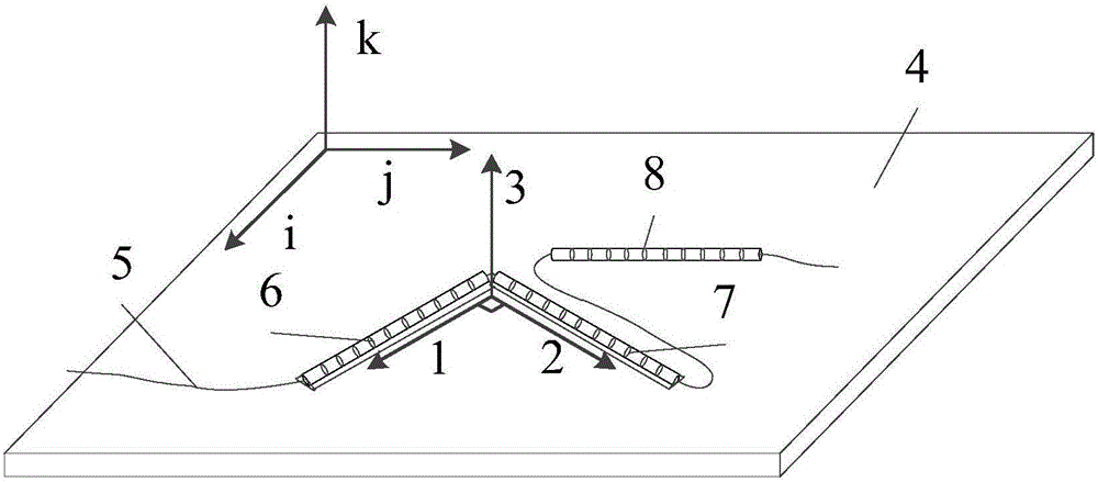
[0069] Step 1. Definition of the coordinate system of the composite material surface and the layout of the fiber Bragg grating sensor network and the establishment of the fiber FBG coordinate system; the fiber Bragg grating sensor network includes two mutually perpendicular fiber Bragg grating sensors FBG1, FBG2 and a freely placed temperature compensation grating sensor FBG3;

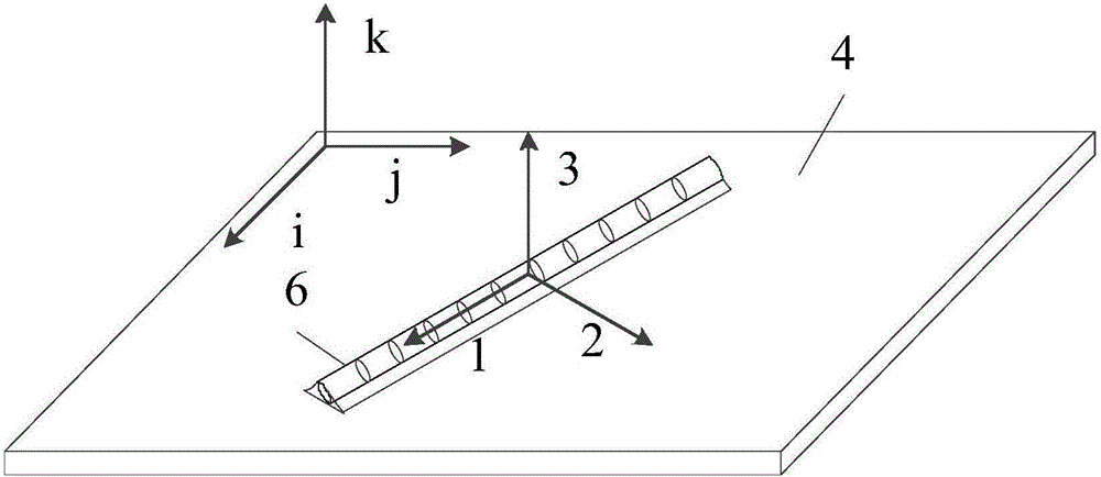
[0070] Two fiber grating sensors FBG1 and FBG2 perpendicular to each other are respectively pasted on the surface of the composite material board structure to be tested. Establish two three-dimensional Cartesian coordinate systems, such as figure 1 As shown, they are: the optical fiber FBG coordinate system, with FB...


PUM


Abstract

The invention provides a method for calculating thermal expansion coefficient of a composite plate based on an optical fiber strain conversion matrix and belongs to the field of structure health monitoring. The method provided by the invention comprises the following steps: firstly, defining a coordinate system of the surface of a to-be-tested composite plate and arranging an optical fiber sensing network; secondly, constructing a conversion matrix between thermal strain received by a grating and central wavelength shift; thirdly, constructing a conversion matrix between thermal strain of a composite plate structure and the central wavelength shift of an optical fiber grating; fourthly, acquiring a response signal of an optical fiber grating sensor under variable temperature condition; fifthly, calculating thermal strains in i and j directions of a to-be-tested composite plate structure; and sixthly, determining the thermal expansion coefficient of the to-be-tested composite plate structure. The calculation method provided by the invention builds a thermal expansion coefficient calculation model for the composite plate structure and can determine the thermal expansion coefficient of the composite plate structure in the to-be-tested direction. The method provided by the invention is simple and easy, high in accuracy and good in reliability.

Description

technical field [0001] The invention belongs to the field of structural health monitoring, and specifically proposes a method for measuring the thermal expansion coefficient of a composite material plate structure based on an optical fiber strain conversion matrix. Background technique [0002] Composite material is a new type of advanced structural material, which has good dimensional stability and durability in special environments, and has been widely used in engineering. Thermal expansion coefficient is one of the important physical properties of materials. It is used to directly characterize the volume change of substances caused by temperature changes, and has an important impact on structural health monitoring and service life assessment. When under the action of temperature load, the structure undergoes heat radiation and conduction in the radial direction, and due to the existence of temperature gradient inside the material, thermal strain will inevitably occur, res...

Claims


Application Information

Patent Timeline
IPC IPC(8): G01N25/16
CPCG01N25/16
Inventor 曾捷马驰张景川张旭苹王珂冯翔宇周林
Owner NANJING UNIV OF AERONAUTICS & ASTRONAUTICS
Learn More