
Wearable portable air conditioning fan

An air-conditioning fan and portable technology, applied in the field of portable refrigeration devices, can solve the problems of large pressure loss in the delivery pipe, inability to dehumidify, and inability to miniaturize the fan, and achieve the effects of light weight, convenient use, and simple operation

Inactive Publication Date: 2016-12-07
上海典唯科技有限公司
View PDF8 Cites 2 Cited by
  • Summary
  • Abstract
  • Description
  • Claims
  • Application Information

AI Technical Summary

Problems solved by technology

The first solution can only achieve the effect of cooling, but cannot dehumidify; while the second solution is difficult to achieve portable wearing effect due to the large pressure loss of the delivery pipe and the corresponding problems such as the inability to miniaturize the fan
Both of the above two solutions require custom-made specific clothing, and it is difficult to clean the clothing. You must wear this special clothing to achieve the cooling effect.

Method used


Image

  • Wearable portable air conditioning fan
  • Wearable portable air conditioning fan
  • Wearable portable air conditioning fan

Examples


Embodiment 1

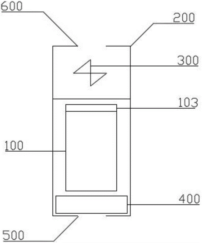
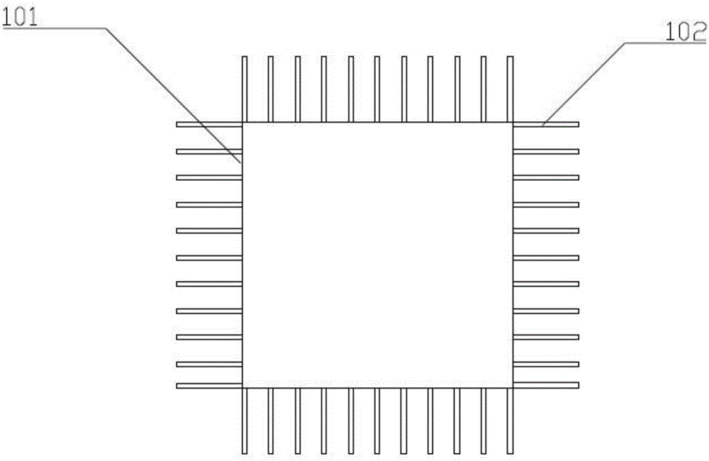
[0039] like figure 1As shown, it is a portable air-conditioning fan provided by the present invention, which includes a cooling storage unit 100 for placing a cooling source and dissipating the cooling energy released by the phase change of the cooling source, wrapping the cooling storage unit 100 And the heat preservation bag 200 with the air inlet 500 at the bottom and the fan 300 for sucking the cold energy from the heat preservation bag 200 out of the heat preservation bag 200 through the air outlet 600 on the upper part of the heat preservation bag 200, wherein, The cold storage unit 100 includes a cooling cavity 101 that is hollow and has no top and accommodates the cooling source, and several metal cooling fins wrapped outside the cooling cavity 101 and dissipating the cooling energy into the heat preservation bag 200 The sheet 102 is movably connected to the top of the cooling chamber 101 and prevents the volume change caused by the phase change of the cooling source. ...

Embodiment 2

[0048] On the basis of the structure of Example 1, the top cover structure is further improved:

[0049] The top cover includes,

[0050] On the air inlet side, the air flow enters the air inlet side through the mesh structure. The air hole includes a drainage portion for introducing the air flow and a steady flow portion for outputting the air flow from the drainage portion. The drainage portion has an "eight"-shaped structure. The top of the "eight"-shaped structure extends along the air outlet direction to form the steady flow portion;

[0051] accommodating area, the fan 300 is arranged in the accommodating area between the air inlet side and the air outlet side;

[0052] On the air outlet side, the air flow is blown out from the air outlet side through the accommodating area, and the air outlet side is a bell-mouth type wind guide hood movably connected to the accommodating area, which is used to guide the air flow;

[0053] The air flow after passing through the air pa...


PUM


Abstract

The invention provides a wearable portable air conditioning fan comprising a cold storage unit used for accommodating a cold source and provided with an opening in each of the bottom and the top, a thermal insulation bag used for wrapping the outside of the cold storage unit and provided with an air inlet in the bottom and a draught fan used for exhausting air entering from the air inlet from an air outlet formed in the top of the thermal insulation bag; the cold storage unit internally comprises a heat radiating unit which is arranged adjacent to the cold source and is longitudinally and uniformly distributed with a plurality of heat radiating fins; and an air flow passage is formed between every two adjacent heat radiating fins, wherein each of the heat radiating fins extends from the bottom to the top of the cold storage unit along the height direction, and an air flow in the air flow passage is blown out after being subjected to heat exchange through being in contact with the heat radiating fins. The wearable portable air conditioning fan provided by the invention has no special requirements for clothing and is light in weight, simple in operation and small in size so as to be portable, wearable and convenient to use.

Description

technical field [0001] The invention relates to a refrigeration device, in particular to a portable refrigeration device that can be worn around. Background technique [0002] The development of air-conditioning systems has solved the thermal comfort problem of most indoor environments, but its application is limited indoors; in many cases, humans must work in outdoor high-temperature environments, such as traffic police, construction site workers, fruit pickers, military personnel and others. Workers such as outdoor athletes. Working and living in a high temperature and high humidity environment often brings a strong sense of discomfort to people, and even endangers the safety of people's lives. [0003] In order to avoid heat stroke, it is necessary to take certain measures to cool and adjust the temperature of the microenvironment close to the human skin surface or under clothing. The existing technology provides two solutions for this: the first is to use the phase cha...

Claims


Application Information

Patent Timeline
IPC IPC(8): F24F5/00F24F13/00
CPCF24F5/0017F24F13/00F24F2221/12Y02E60/14
Inventor 邹钺刘赟
Owner 上海典唯科技有限公司
Learn More