Pallet Structure for Workpiece Carrying

A pallet and workpiece technology, applied in the field of pallet structure carrying workpieces, can solve the problems of shortening working time and cost, and achieve the effect of improving function and effect

Inactive Publication Date: 2018-05-11
USUN TECH CO LTD
View PDF5 Cites 0 Cited by
  • Summary
  • Abstract
  • Description
  • Claims
  • Application Information

AI Technical Summary

Problems solved by technology

[0004] However, due to the needs of each processing process, the above-mentioned workpieces must be frequently transported, displaced, and aligned. Generally, a protective frame is installed on the workpiece or a pallet is used to carry it. The protective frame or pallet prevents the workpiece. In the process of conveying, if there are scratches, cracks, or the edge of the workpiece is cracked or damaged due to collision, it can be conveyed to each station for processing by means of the conveying device, or the processed workpiece can be conveyed to Other workstations carry out the follow-up production process, but the pallet can only provide a single workpiece load at a time, which will not only cause the conveying device to be too compact in the process of transporting multiple pallets, but also make the subsequent pallets must be processed before being transported to each workstation. Only when the conveying action is suspended can the robot arm be used to pick up or place the moving action, resulting in the inability to shorten the working time and cost more effectively. With the diversification of processing methods and the complexity of the process, the structure design of the pallet carrying the workpiece , it is also necessary to consider the needs of production line automation and special manufacturing processes, such as carrying different workpiece materials (such as metal or plastic), stacking, conveying, positioning and direction recognition, and processing tools, cleaning machines, etc. to carry out follow-up on workpieces The manufacturing process or production process to improve the practicability and applicability of the use of pallets is the key to research and improvement for those engaged in this industry.

Method used


Image

  • Pallet Structure for Workpiece Carrying
  • Pallet Structure for Workpiece Carrying
  • Pallet Structure for Workpiece Carrying

Examples


Embodiment Construction

[0034] In order to achieve the above-mentioned purpose and effect, the technical means and the structure thereof adopted in the present invention are hereby illustrated in detail with respect to preferred embodiments of the present invention. Its structure and function are as follows, so as to fully understand.

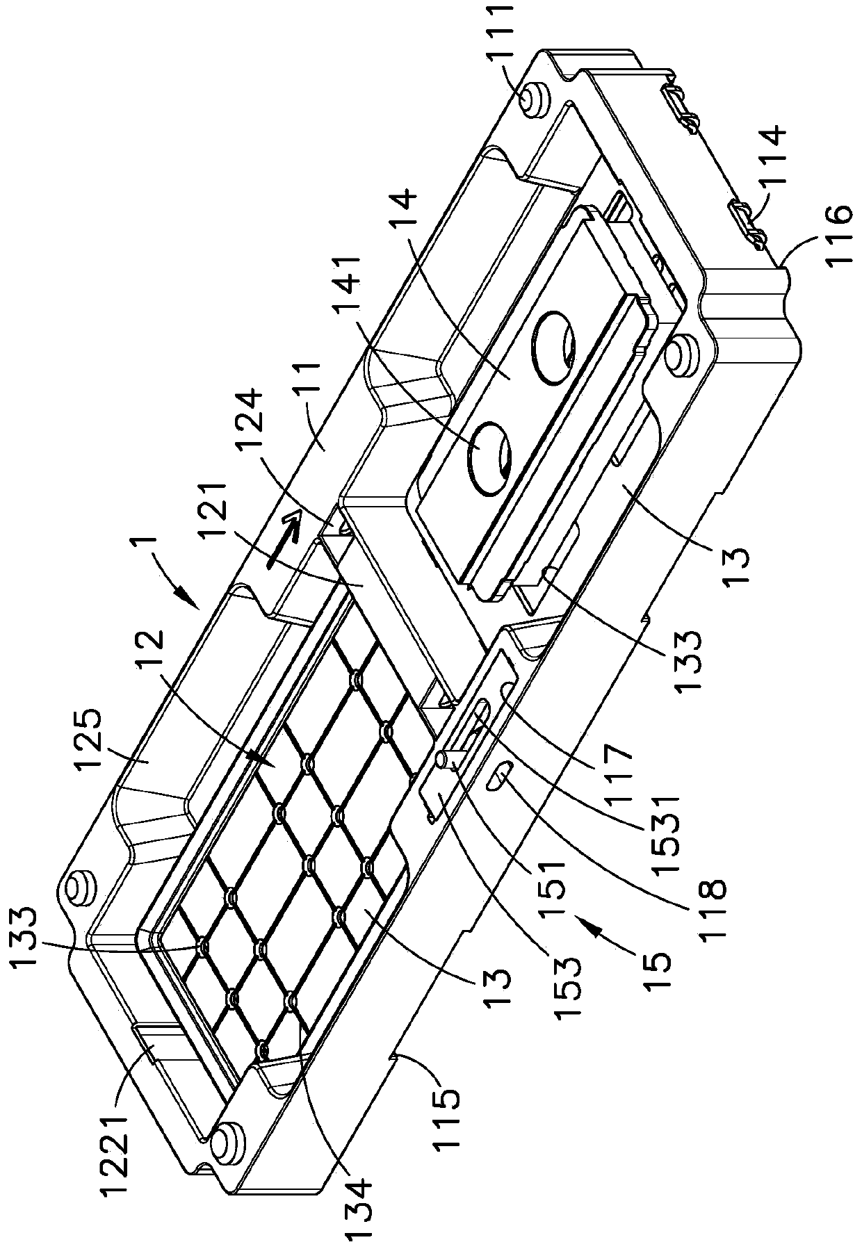
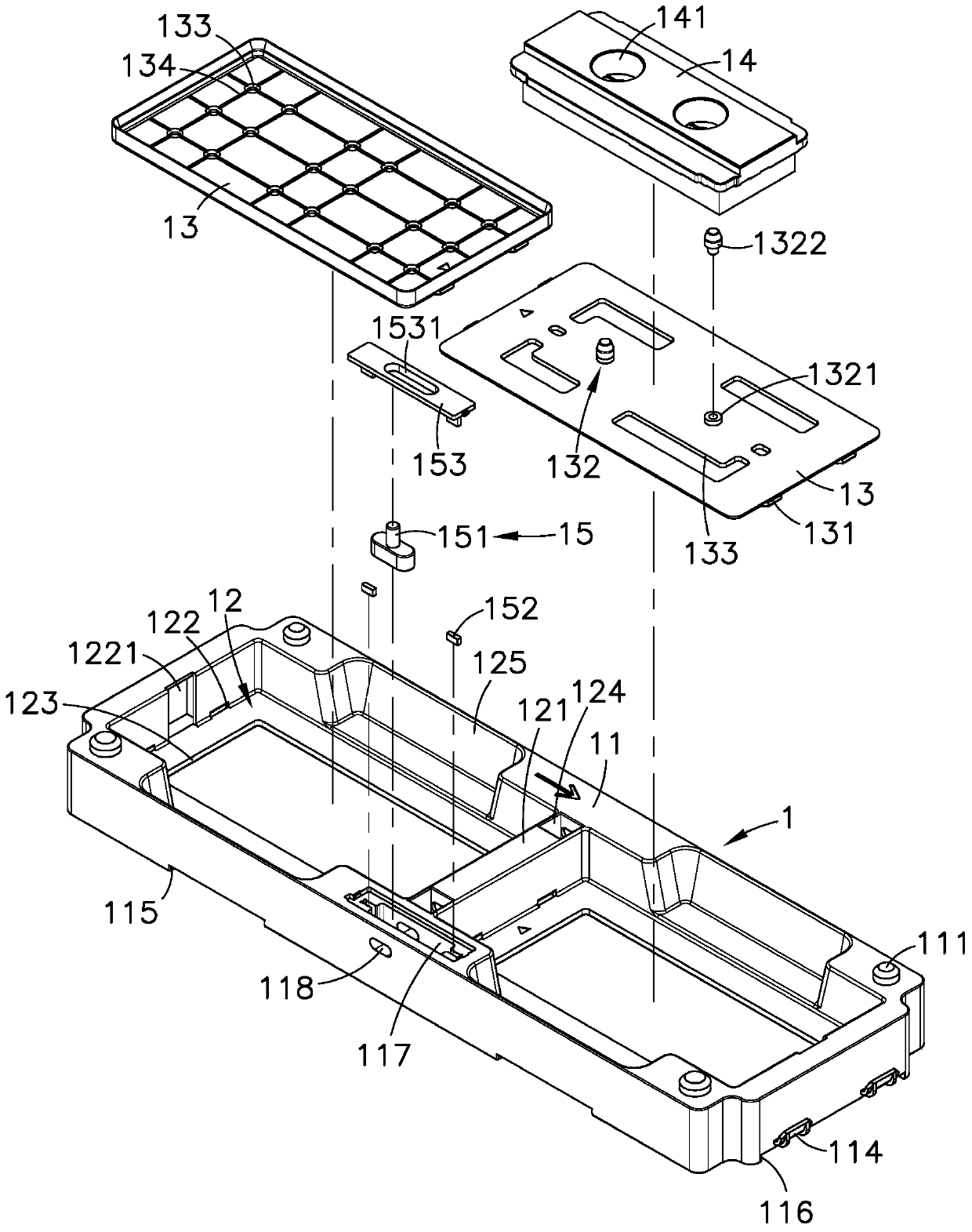
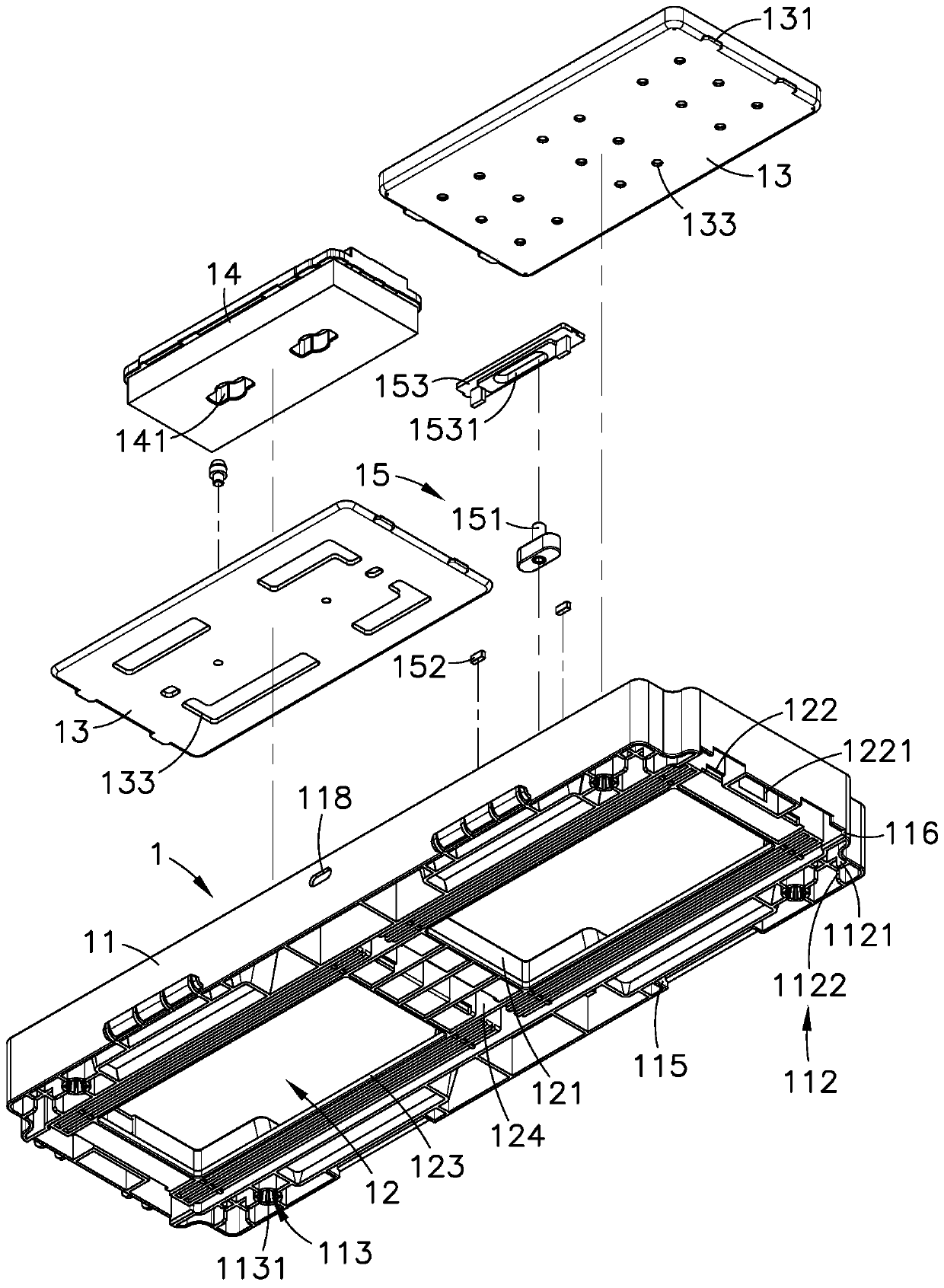
[0035] see figure 1 , 2 , 3, and 4 are respectively the three-dimensional appearance diagram, the three-dimensional exploded view, the three-dimensional exploded view of another viewing angle and the three-dimensional exploded view of the pallet and the workpiece of the preferred embodiment of the present invention. It can be clearly seen from the figure that the present invention In order to include the tray 1, the tray 1 has a rectangular base 11, inside the base 11 is formed a plurality of recessed accommodating grooves 12 arranged along the long side direction for the positioning of the workpiece 2. A partition 121 is formed between adjacent accommodating grooves...


PUM


Abstract

The present invention provides a tray structure for carrying workpieces. A partition is formed between two adjacent accommodation grooves inside the base of the tray, and a recess is provided on the top of the base adjacent to the accommodation groove and the partition. There is an embedding groove, and the identification device’s lever is installed inside the embedding groove, and magnetic elements are respectively installed on both sides of the embedding groove, due to the different process requirements or differences in the processing process during the tray conveying process, it is easy to produce mixing situations , it can rely on the mechanical arm to push the sliding displacement of the lever on the identification device, and record the orientation of the lever to determine the current processing state of the workpiece, and the magnetic element can be magnetically adsorbed on the lever to form a positioning, so that the lever will not Arbitrary sliding or falling off occurs to avoid the problem of incorrect recording and misoperation of the mechanical arm caused by the lever not being in the correct position, so as to improve its overall use function and effect.

Description

technical field [0001] The invention relates to a tray structure for carrying workpieces, in particular to a recessed embedding groove at the top of the base of the tray adjacent to the accommodating groove and the partition, and a lever for an identification device and a positioning rod located in the embedding groove are arranged inside the embedding groove. The magnetic elements on both sides of the groove can use the mechanical arm to push the lever and record the orientation to determine the current processing status of the workpiece, so as to avoid the mixing of materials due to different process requirements or differences in the processing process during pallet transportation. Background technique [0002] By the way, today's manufacturing industry is facing labor shortages, rising awareness of environmental protection, rising labor and operating costs, and pressure from labor-intensive to technology-intensive transformation. Most manufacturers respond to the cost by ...

Claims


Application Information

Patent Timeline
Patent Type & Authority Patents(China)
IPC IPC(8): B65D19/02B65D21/02
Inventor 黄秋逢苏泰瑞
Owner USUN TECH CO LTD
Why Eureka
Try Eureka