Pneumatic tire repairing device

A tire repair and pneumatic technology, applied in the direction of tires, other household appliances, household appliances, etc., can solve the problems of increased movement paths, wasted time in assembly, and the speed of tire repair fluid cannot be accelerated.

Inactive Publication Date: 2016-12-07
BETO ENG & MARKETING
View PDF10 Cites 1 Cited by
  • Summary
  • Abstract
  • Description
  • Claims
  • Application Information

AI Technical Summary

Problems solved by technology

[0003] One, this tire repairing device must be provided with valve core 23 in intake passage 200, guide passage 220, perforation 221 and slide block 26 are established in guide tube 22, and intake passage 200 is provided with plug block 24, so integral part is very Many, and the assembly is quite time-consuming, so the overall manufacturing cost does not meet the market requirements of disposable
[0004] 2. When this prior art is used upright, the high-pressure gas is pumped into the tank body 1. The high-pressure gas pushes the valve core 23 from the air intake hole 20 into the air intake channel 200, and flushes the plug 24, and the gas enters the tank. In the body 1, the tire sealant B produces foaming action, so that the tire sealant B enters the diversion tube 22 along the suction pipe 25, and pushes the check valve 210, and then injects it from the through hole 212 of the outlet 21 through a connecting tube In the tire, the suction pipe 25 is mainly used for outputting the tire sealant after pressurization, so the tire sealant has to go around a long way through the suction pipe 25 before entering the diversion channel 220, and its movement path is greatly increased, but when it is used upside down, Only the liquid pressure of the tire sealant itself can be used, and the high-pressure gas introduced by it cannot achieve effective pressurization; therefore, when repairing a flat tire, no matter whether it is upright or upside down, the speed of injecting the tire sealant cannot be achieved. Speed ​​up, there is a need for improvement

Method used


Image

  • Pneumatic tire repairing device
  • Pneumatic tire repairing device
  • Pneumatic tire repairing device

Examples


Embodiment Construction

[0044] In order to further explain the technical solution of the present invention, the present invention will be described in detail below through specific examples.

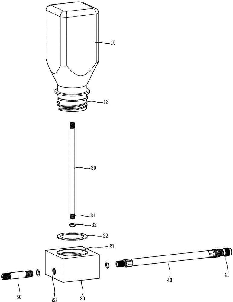
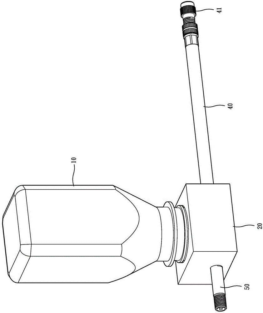
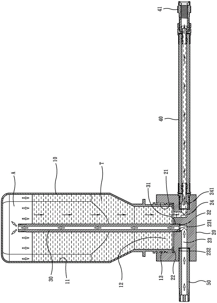
[0045] Please see Figure 1 to Figure 4 , the present invention includes a bottle body 10, a valve cover 20, an air guide tube 30, a throat pipe 40 and a pipe joint 50; wherein:

[0046] The bottle body 10 has a chamber 11 inside, and its bottom end has a bottle mouth 12 that communicates with the inside and outside of the chamber 11, and an external thread 13 is provided on the outer periphery of the bottle mouth 12;

[0047] The valve cover 20 has an internal screw hole 21 that can be assembled with the external thread 13, so that the valve cover 20 can be a detachable closed bottle mouth 12. In order to maintain the sealing effect, its bottle mouth 12 and the internal screw hole 21 are in contact A first seal ring 22 is installed at the connected part; the valve cover 20 is also provided with an air inlet p...


PUM


Abstract

The invention discloses a pneumatic tire repairing device. The bottom end of a bottle body is provided with a bottle opening enabling the interior and the exterior of the bottle body to communicate, and the bottle opening is sealed through a detachable valve deck. A containing chamber of the bottle body is filled with tire repairing liquid, and an air chamber is formed between the top edge of the containing chamber and the liquid level of the tire repairing liquid. The valve deck is provided with an air inlet channel and a flow guiding channel, and the air inlet channel and the flow guiding channel enable the interior and the exterior of the containing chamber to communicate. The air inlet channel is externally connected with an air source. One end of the flow guiding channel communicates with the bottom end of the bottle opening. The air inlet channel is provided with an air guiding pipe, and the top end of the air guiding pipe is kept protruding out of the liquid level of the tire repairing liquid to communicate with the air chamber on the top edge of the containing chamber. The flow guiding channel is externally connected with a throat pipe. An air nozzle which can be connected with a valve core of a tire in an assembled mode is mounted on the throat pipe. In this way, the purposes of simplified structure, stable pressure and high tire repairing liquid injection speed are achieved.

Description

technical field [0001] The invention relates to a pneumatic tire repair device, in particular to a pneumatic tire repair device which injects tire sealant fluid into the tire for rapid repair. Background technique [0002] prior art such as Figure 5 , Image 6 As shown, the existing tire repairing device has the following shortcoming at least: [0003] One, this tire repairing device must be provided with valve core 23 in intake passage 200, guide passage 220, perforation 221 and slide block 26 are established in guide tube 22, and intake passage 200 is provided with plug block 24, so integral part is very There are many, and the assembly is quite time-consuming, so the overall manufacturing cost does not meet the market requirements of using and throwing away. [0004] 2. When this prior art is used upright, the high-pressure gas is pumped into the tank body 1. The high-pressure gas pushes the valve core 23 from the air intake hole 20 into the air intake channel 200, and...

Claims


Application Information

Patent Timeline
Patent Type & Authority Applications(China)
IPC IPC(8): B29C73/02B29L30/00
Inventor 王罗平
Owner BETO ENG & MARKETING
Why Eureka
Try Eureka