
Control system of sawing, drilling and milling machining production line

A control system and milling technology, applied in the direction of wood processing appliances, manufacturing tools, multi-purpose machinery, etc., can solve the problems of low degree of automation, unsafe accidents, labor and material consumption, etc., to save labor and materials, high safety factor Effect

Inactive Publication Date: 2016-12-07
美克国际家私(天津)制造有限公司
View PDF6 Cites 2 Cited by
  • Summary
  • Abstract
  • Description
  • Claims
  • Application Information

AI Technical Summary

Problems solved by technology

[0002] As we all know, in the process of wood processing, it is often necessary to perform sawing, drilling, and milling operations on strip-shaped plates; at present, people have designed electric saws, electric drills, and milling machines for the above three processes; in the actual processing process In the process, people need to transport the strip plate to the relevant equipment, and then manually load the material, and manually control the relevant equipment to complete the corresponding process. Obviously, this traditional technology has a low degree of automation and consumes a lot of manpower and materials; at the same time, manual Operations often lead to many unsafe accidents; therefore, it is particularly important to design and develop a control system for sawing, drilling and milling production lines with a high degree of automation, saving manpower and materials, and having a higher safety factor

Method used


Image

  • Control system of sawing, drilling and milling machining production line

Examples


Embodiment Construction

[0015] In order to further understand the invention content, characteristics and effects of the present invention, the following examples are given, and detailed descriptions are as follows in conjunction with the accompanying drawings:

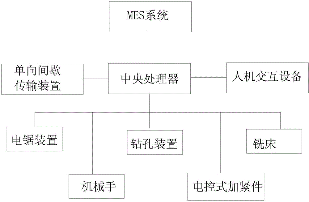
[0016] see figure 1 , a control system for a sawing, drilling and milling production line, the sawing, drilling and milling production line includes a one-way intermittent transmission device for driving a strip-shaped plate to run, an electric saw device for sawing a strip-shaped plate, and an electric saw device for sawing a strip-shaped plate A drilling device for drilling holes in strip-shaped plates, a milling machine for milling strip-shaped plates; wherein: the one-way intermittent transmission device includes two parallel transmission belts, and a belt that drives the two transmission belts to move synchronously A stepper motor, with electronically controlled tightening parts for clamping strip-shaped plates at equal intervals on the ...


PUM


Abstract

The invention discloses a control system of a sawing, drilling and milling machining production line. The sawing, drilling and milling machining production line comprises a one-way intermittent transmission device for driving a strip-shaped plate to move, an electric saw device for sawing the strip-shaped plate, a drilling device for drilling the strip-shaped plate, and a milling machine for milling the strip-shaped plate. The one-way intermittent transmission device comprises two conveyor belts arranged in parallel, and a stepping motor for driving the two conveyor belts to move synchronously. Electric control clamping pieces for clamping the strip-shaped plate are arranged on the conveyor belts at equal intervals. The control system at least comprises a field controller and an MES for carrying out remote data interaction with the field controller. The field controller is used for controlling the working state of the stepping motor, the working state of the electric saw device, the working state of the drilling device, the working state of the milling machine and the working state of the electric control clamping pieces. The field controller comprises a central processor and man-computer interaction equipment. The central processor and the man-computer interaction equipment are connected through a data line.

Description

technical field [0001] The invention relates to the technical field of furniture processing equipment, in particular to a control system for a sawing, drilling and milling production line. Background technique [0002] As we all know, in the process of wood processing, it is often necessary to perform sawing, drilling, and milling operations on strip-shaped plates; at present, people have designed electric saws, electric drills, and milling machines for the above three processes; in the actual processing process In the process, people need to transport the strip plate to the relevant equipment, and then manually load the material, and manually control the relevant equipment to complete the corresponding process. Obviously, this traditional technology has a low degree of automation and consumes a lot of manpower and materials; at the same time, manual Operations often lead to many unsafe accidents; therefore, it is particularly important to design and develop a control system...

Claims


Application Information

Patent Timeline
IPC IPC(8): B27C9/00
CPCB27C9/00
Inventor 邱小勇许海
Owner 美克国际家私(天津)制造有限公司
Learn More