
Automatic placing and storing device for cylindrical rollers

A technology of automatic discharging and storage device, applied in the direction of transportation and packaging, conveyor objects, etc., can solve the problems of low blanking efficiency, safety production accidents, laborious manual handling, etc.

Inactive Publication Date: 2020-10-16
定远特尔润滚子有限公司
View PDF7 Cites 0 Cited by
  • Summary
  • Abstract
  • Description
  • Claims
  • Application Information

AI Technical Summary

Problems solved by technology

[0004] However, after the milling process, the cylindrical roller material needs to be placed in the material frame during the blanking process, and the material frame with the roller is heavy. In the prior art, the blanking method adopted is to place the roller material Placed in the material frame, after the material frame is fully loaded, the material frame is transported to replace the spare material frame. This method not only has low working efficiency, but also requires manual handling, and the weight of the material frame is relatively large. During the process of transportation, it is easy to cause safety production. ACCIDENT

Method used


Image

  • Automatic placing and storing device for cylindrical rollers
  • Automatic placing and storing device for cylindrical rollers
  • Automatic placing and storing device for cylindrical rollers

Examples


Embodiment Construction

[0046] The embodiments of the present invention are described in detail below. This embodiment is implemented on the premise of the technical solution of the present invention, and detailed implementation methods and specific operating procedures are provided, but the protection scope of the present invention is not limited to the following implementation example.

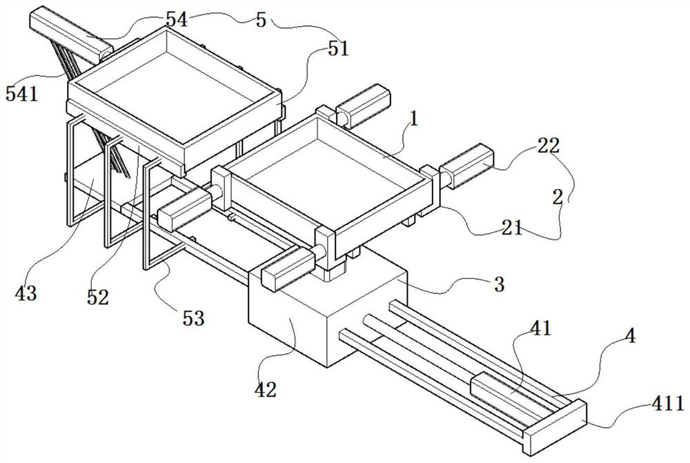
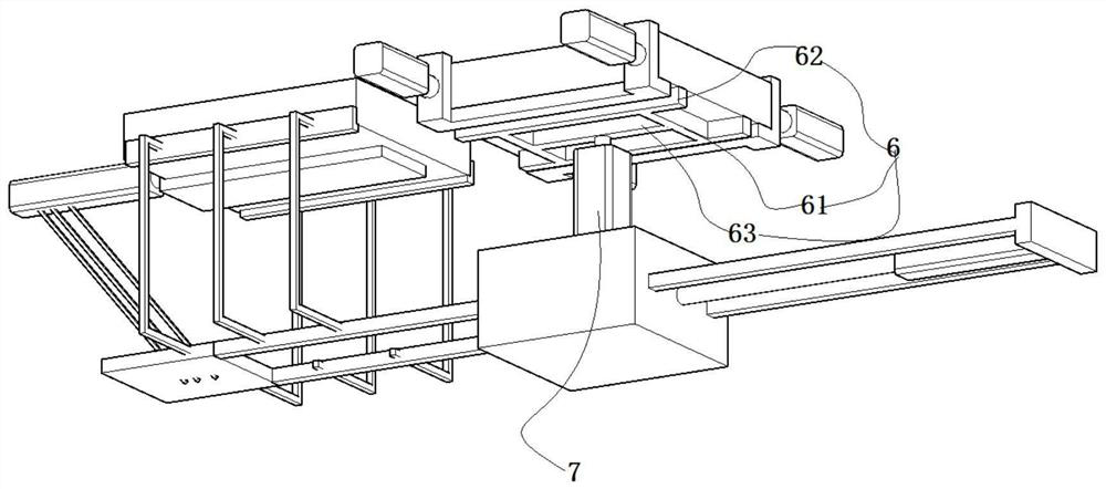
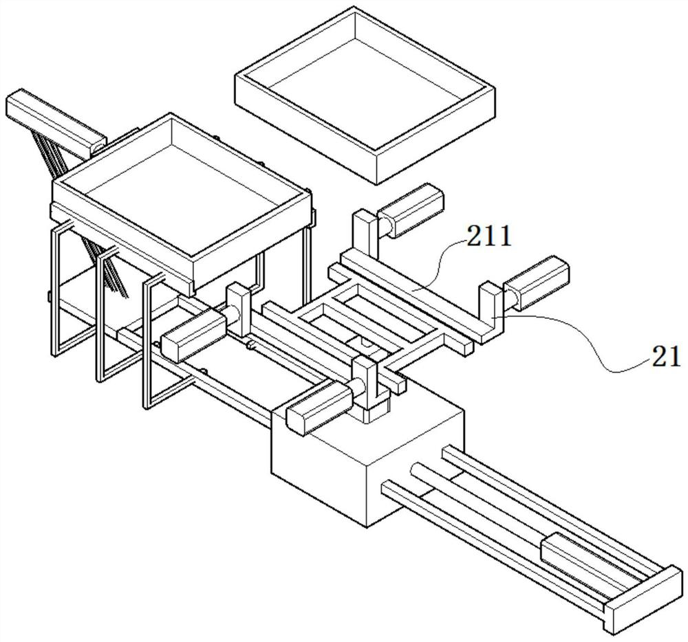
[0047] Such as Figure 1-7 As shown, a cylindrical roller automatic discharge storage device includes a bottom sliding frame 4; a sliding seat 3 is slidably connected to the bottom sliding frame 4, and a sliding seat 41 is mounted on the sliding seat 3. The sliding seat 41 drives the sliding seat 3 to move; the top of the sliding seat 3 is fixedly connected with a second cylinder 7, and the piston rod of the second cylinder 7 is fixedly connected with a support frame 6; the top of the support frame 6 supports a clip Holder 2;

[0048] The above-mentioned clamping assembly 2 includes a discharge frame 1, and the f...


PUM


Abstract

The invention discloses an automatic placing and storing device for cylindrical rollers. The automatic placing and storing device comprises a bottom sliding frame; a sliding seat is connected to the bottom sliding frame in a sliding mode, and a first air cylinder is assembled on the sliding seat; the sliding seat is driven to move through the first air cylinder; the top of the sliding seat is fixedly connected with a second air cylinder, and a piston rod of the second air cylinder is fixedly connected with a supporting frame; a clamping assembly is supported by the top of the supporting frame;the clamping assembly comprises a material placing frame, clamping rods are limited on the front side and the rear side of the bottom of the material placing frame, and vertically-upward limiting ends are arranged at the left ends and the right ends of the clamping rods; third air cylinders are fixedly connected to the outer side walls of the limiting ends; and the automatic placing and storing device for the cylindrical rollers further comprises a standby material frame pushing assembly. With the adoption of the device component design, manual material carrying is not needed, meanwhile, automatic roller material loading is realized through the device component design, and the material roller loading and discharging efficiencies are greatly improved through the device component design.

Description

technical field [0001] The invention relates to the field of cylindrical roller processing devices, in particular to an automatic discharging storage device for cylindrical rollers. Background technique [0002] Cylindrical rollers are the functional parts of roller bearings, and the rotation of the bearing is realized by setting cylindrical rollers between the inner ring and the outer ring of the bearing. [0003] In the prior art, in the process of cylindrical rollers, such as rollers with high machining precision, CNC lathes are mostly used for processing, and CNC lathes mill the rollers. In the process of CNC machining, in order to reduce the Friction, often during the milling process, the milling fluid is sprayed while the milling process is performed. [0004] However, after the milling process, the cylindrical roller material needs to be placed in the material frame during the blanking process, and the material frame with the roller is heavy. In the prior art, the bl...

Claims


Application Information

Patent Timeline
IPC IPC(8): B65G47/74B65G47/82
CPCB65G47/74B65G47/82
Inventor 张忠
Owner 定远特尔润滚子有限公司
Learn More