A rough and fine composite CNC machining center machine tool

A technology of machining centers and machine tools, which is applied in the direction of metal processing machinery parts, metal processing equipment, manufacturing tools, etc., can solve the problems of increasing equipment investment, low speed, time-consuming, etc., and achieve the effect of great practical value

Active Publication Date: 2019-02-01
安徽霍仕达智能科技股份有限公司
View PDF7 Cites 0 Cited by
  • Summary
  • Abstract
  • Description
  • Claims
  • Application Information

AI Technical Summary

Problems solved by technology

[0002] Through the research on standard CNC machining center machine tools, it is found that the current standard machining center machine tools on the market, in metal cutting processing, large cutting volume, heavy cutting and high-speed high-precision machining cannot be completed on the same machine tool at the same time, the current market standard Advanced roughing machine tool, the main shaft uses full gear transmission, low speed and high noise
The current standard high-speed machines in the market are mostly high in cost and small in chip volume. When using them, rough machining must be carried out first. Often, a machine tool with a hard rail gear drive spindle is used first to rough out parts and components with a large amount of cutting. For the cutting allowance required for some processing, remove the workpiece and put it into a high-speed, high-precision machine tool for precision high-speed processing
This operation requires 2 times of clamping and calibration, and the investment of 2 machine tools, which is time-consuming and increases the investment of equipment

Method used


Image

  • A rough and fine composite CNC machining center machine tool
  • A rough and fine composite CNC machining center machine tool
  • A rough and fine composite CNC machining center machine tool

Examples


Embodiment Construction

[0019] The embodiments of the present invention will be described in detail below with reference to the accompanying drawings, but the present invention can be implemented in many different ways defined and covered by the claims.

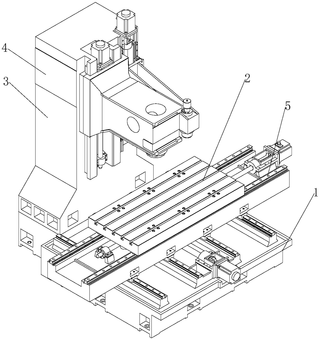
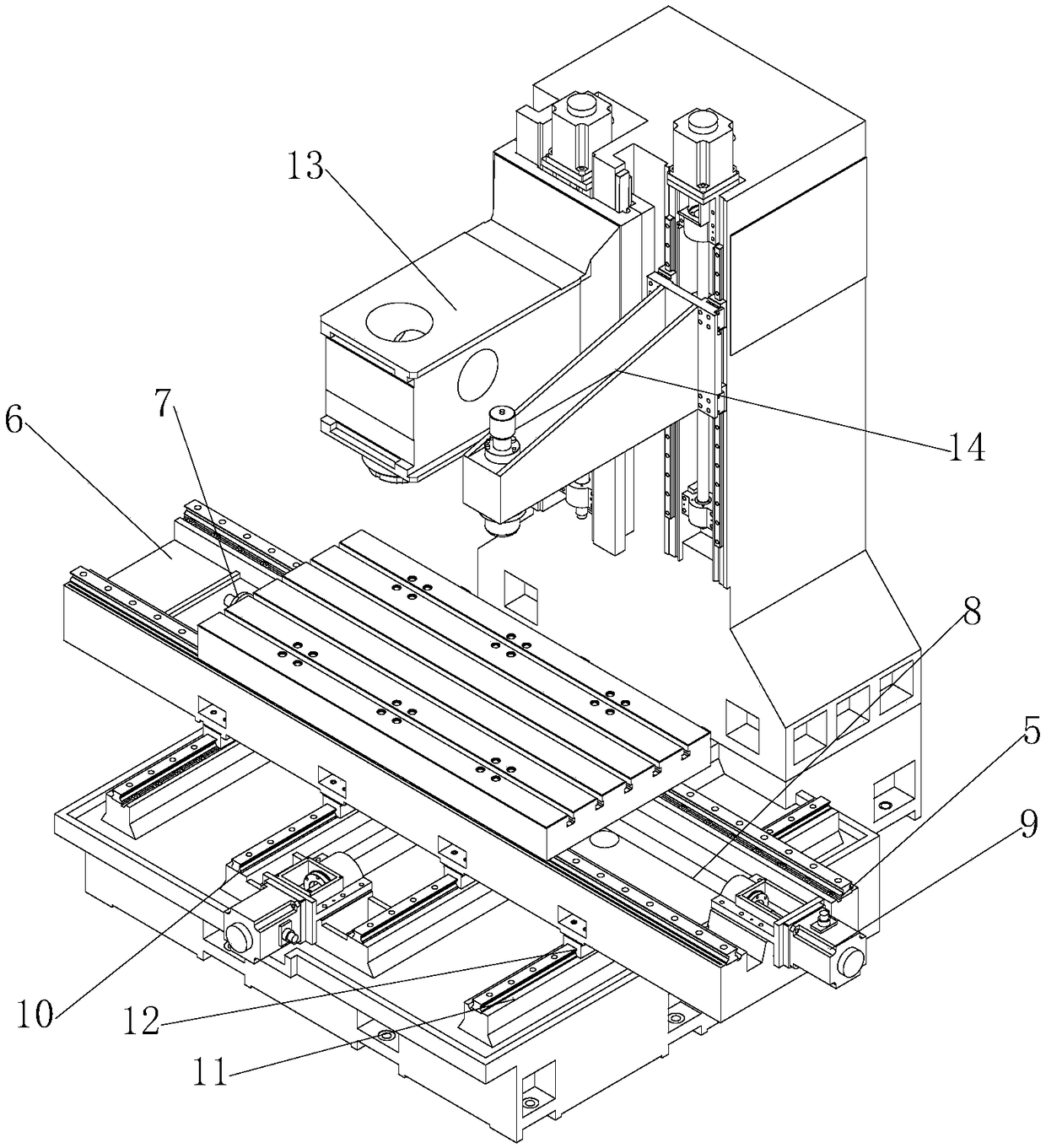
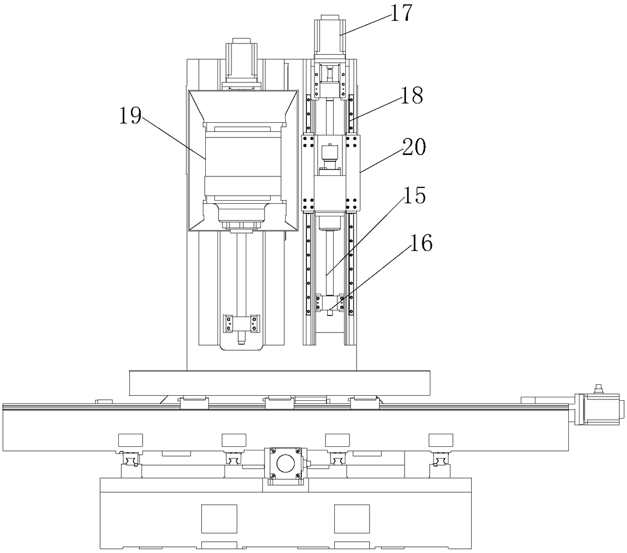
[0020] As shown in the accompanying drawings, a rough-fine composite CNC machining center machine tool includes a base 1, a mobile device installed on the base 1, a workbench 2 movably installed on the mobile device, a column 3 installed on the back of the base 1, and a The thick and thin double-head composite structure on the column 3, the power device and the automatic tool changer 4 installed on the column 3, in order to improve the stability of the device, increase the length and width of the bottom surface of the base 1, and increase the length of the bottom surface of the column 3 with width.

[0021] The mobile device includes a horizontally installed linear track 5 and a vertically installed linear track 5. The linear track 5 includes a sadd...


PUM


Abstract

The invention discloses a rough-precise compound numerical control machining center machine tool which comprises a base, a moving device installed on the base, a worktable movably installed on the moving device, a stand column installed on the back face of the base, a thick-thin double-head composite structure installed on the stand column, a power device and an automatic tool changing device installed on the stand column. According to the rough-precise compound numerical control machining center machine tool, original multi-time clamping can be changed into one-time clamping to complete machining, time is consumed during multiple-time clamping, repeatability of secondary workpiece zero correction is not easy to ensure, the machining precision of a product is affected, and the qualification rate of the product is reduced. According to the rough-precise compound numerical control machining center machine tool, high-speed rough machining and high-speed and high-precision machining can also be achieved while the problems are prevented from happening, two machines are combined into one, the work efficiency is improved, the cost of the enterprise investment can also be greatly reduced, the research and development come from the production practice and the market requirements and conform to the research and development direction, and high practical value is achieved.

Description

technical field [0001] The invention belongs to the mechanical field of numerical control machine tools, and specifically relates to a rough-fine compound numerical control machining center machine tool. Background technique [0002] Through the research on standard CNC machining center machine tools, it is found that the current standard machining center machine tools on the market, in metal cutting processing, large cutting volume, heavy cutting and high-speed high-precision machining cannot be completed on the same machine tool at the same time, the current market standard Advanced roughing machine tool, the main shaft is driven by all gears, with low speed and high noise. The current standard high-speed machines in the market are mostly high in cost and small in chip volume. When using them, rough machining must be carried out first. Often, a machine tool with a hard rail gear drive spindle is used first to rough out parts and components with a large amount of cutting. ...

Claims


Application Information

Patent Timeline
Patent Type & Authority Patents(China)
IPC IPC(8): B23Q1/25B23P23/02B23C3/00
CPCB23C3/00B23C2220/605B23P23/02B23Q1/25
Inventor 高海泉
Owner 安徽霍仕达智能科技股份有限公司
Why Eureka
Try Eureka