
U-shaped beam three-dimensional movable positioning bed suitable for radiotherapy

A three-dimensional movement, radiation therapy technology, applied in the directions of radiation therapy, therapy, X-ray/γ-ray/particle irradiation therapy, etc., can solve the problem of inability to achieve in-situ horizontal rotation, large-scale changes in longitudinal inclination, inability to intelligently control, and simple structure. and other problems, to achieve the effect of compact structure, reasonable design and convenient use

Inactive Publication Date: 2016-12-07
SHANDONG UNIV QILU HOSPITAL
View PDF4 Cites 8 Cited by
  • Summary
  • Abstract
  • Description
  • Claims
  • Application Information

AI Technical Summary

Problems solved by technology

[0002] Although various medical beds in current clinical applications can also be moved by the lower traveling wheels, or the use angles of different segments of the bed board can be adjusted by a mechanical lever mechanism, the structure is too simple to achieve in-situ horizontal rotation and longitudinal inclination. Large-scale changes, three-dimensional adjustment and positioning such as lateral swing of the bed surface, especially cannot intelligently control displacement according to a certain angle or motion trajectory, especially not suitable for regional scanning of a certain lesion area of ​​a patient during radiotherapy and according to a certain To move the patient on the trajectory and realize the scanning irradiation therapy, it is necessary to set the moving speed and irradiation intensity index according to the preset trajectory of the lesion area, so as to realize the precise positioning of the patient by the numerical control of the treatment bed and the scanning displacement therapy

Method used


Image

  • U-shaped beam three-dimensional movable positioning bed suitable for radiotherapy

Examples


Embodiment

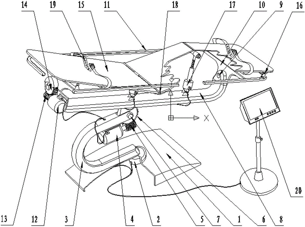
[0014] Embodiment: The structure is shown in the accompanying drawings, consisting of a base 1, a horizontal rotation servo motor 2, a U-shaped beam 3, a longitudinal rocking servo motor 4, a worm A5, a worm wheel A6, a longitudinal rocking shaft 7, a longitudinal main beam 8, and a lateral rocking shaft 9. Beam 10, frame 11, lateral rocking servo motor 12, worm screw B13, worm wheel B14, three-stage bed board 15, rocker arm bracket 16, electric lifting screw 17, bed board hinge 18, restraint fixing belt 19 and intelligent controller 20, etc. Composed of 20 parts, among them, the horizontal rotation servo motor 2 is set on the base 1, and the motor shaft is connected to the lower end of the U-shaped beam 3, and the upper end of the U-shaped beam 3 is connected to the longitudinal main beam 8 through the longitudinal rocking shaft 7 and the worm wheel A6. Hinged, and the upper end of the worm gear A is connected with the longitudinal main beam 8 as a whole, and the upward tilted...


PUM


Abstract

The invention relates to a U-shaped beam three-dimensional movable positioning bed suitable for radiotherapy and belongs to the manufacturing technical field of novel medical auxiliary equipment. The U-shaped beam three-dimensional movable positioning bed comprises the following 20 components: a base, a horizontal rotating servo motor, a U-shaped beam, a longitudinal swinging servo motor, a worm A, a worm gear A, a longitudinal swinging shaft, a longitudinal main beam, a transverse swinging shaft, a cross beam, a frame, a transverse swinging servo motor, a worm B, a worm gear B, a three-section type bed board, a rocker arm support, an electric lifting screw, a bed board hinge, constraint fixing belt, an intelligent controller and the like. During usage, the working power supply of the intelligent controller is switched on, and an operation track control program is preset according to the irradiation treatment requirements of a specific patient. After that, an operation switch is turned on. The program of the U-shaped beam three-dimensional movable positioning bed can be preset to realize the scanning motions of different tracks or realize the positioning operation on different irradiation parts. The U-shaped beam three-dimensional movable positioning bed has the advantages of being reasonable in design, compact in structure, convenient to use and the like.

Description

technical field [0001] The invention relates to a U-shaped beam three-dimensional mobile positioning bed suitable for radiotherapy, and belongs to the technical field of new medical auxiliary equipment manufacturing. Background technique [0002] Although various medical beds in current clinical applications can also be moved by the lower traveling wheels, or the use angles of different segments of the bed board can be adjusted by a mechanical lever mechanism, the structure is too simple to achieve in-situ horizontal rotation and longitudinal inclination. Large-scale changes, three-dimensional adjustment and positioning such as lateral swing of the bed surface, especially cannot intelligently control displacement according to a certain angle or motion trajectory, especially not suitable for regional scanning of a certain lesion area of ​​a patient during radiotherapy and according to a certain To move the patient on the trajectory and realize the scanning irradiation therapy...

Claims


Application Information

Patent Timeline
IPC IPC(8): A61N5/10
CPCA61N5/1001A61N2005/1097
Inventor 韩立丽王涛胡鹏张文
Owner SHANDONG UNIV QILU HOSPITAL
Learn More