
Ignition device for internal combustion engine

A technology of ignition device and internal combustion engine, which is applied in the direction of engine ignition, internal combustion piston engine, and other devices, and can solve problems such as lack of fire

Active Publication Date: 2016-11-30
DENSO CORP
View PDF8 Cites 4 Cited by
  • Summary
  • Abstract
  • Description
  • Claims
  • Application Information

AI Technical Summary

Problems solved by technology

However, in the technique of Patent Document 2, the discharge is prohibited after blowout is detected, so there is a possibility of misfire

Method used


Image

  • Ignition device for internal combustion engine
  • Ignition device for internal combustion engine
  • Ignition device for internal combustion engine

Examples


Embodiment approach 1

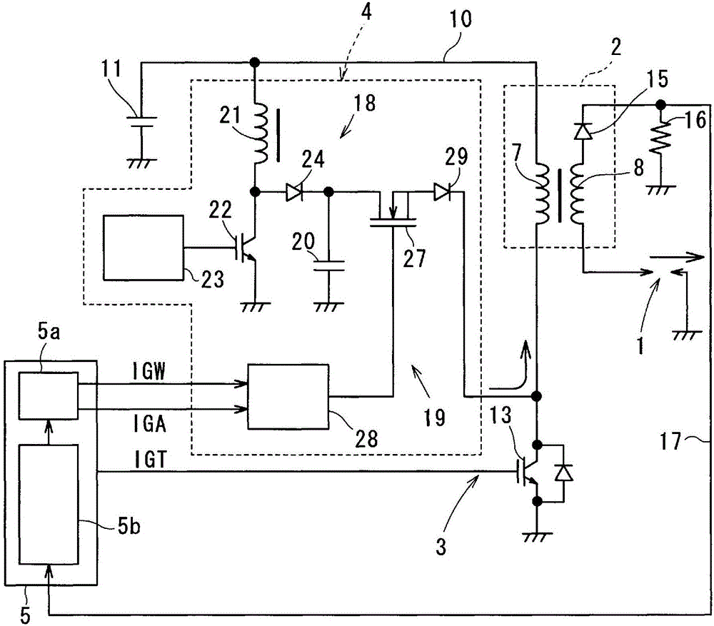
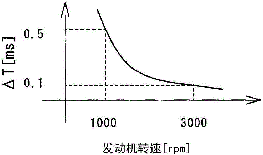
[0045] refer to Figure 1 ~ Figure 3 Embodiment 1 will be described.

[0046] The ignition device in Embodiment 1 is mounted on a spark ignition engine for running a vehicle, and ignites the air-fuel mixture in the combustion chamber at a predetermined ignition timing (ignition timing). In addition, an example of an engine is a lean-burn direct-injection engine that uses gasoline as fuel, and includes a swirl control mechanism that generates a swirl (tumble, swirl, etc.) of the air-fuel mixture in the cylinder.

[0047] The ignition device in Embodiment 1 is a DI (Direct Ignition) type using an ignition coil 2 corresponding to each spark plug 1 of each cylinder.

[0048] The ignition device includes a spark plug 1 , an ignition coil 2 , a main ignition circuit 3 , an energy input circuit 4 , and an ECU 5 .

[0049] The main ignition circuit 3 and the energy input circuit 4 control the energization of the primary coil 7 of the ignition coil 2 based on the instruction signal s...

Embodiment approach 2

[0096] refer to Figure 4 Embodiment 2 will be described. In addition, in Embodiment 2, the same code|symbol as above-mentioned Embodiment 1 represents the same functional thing.

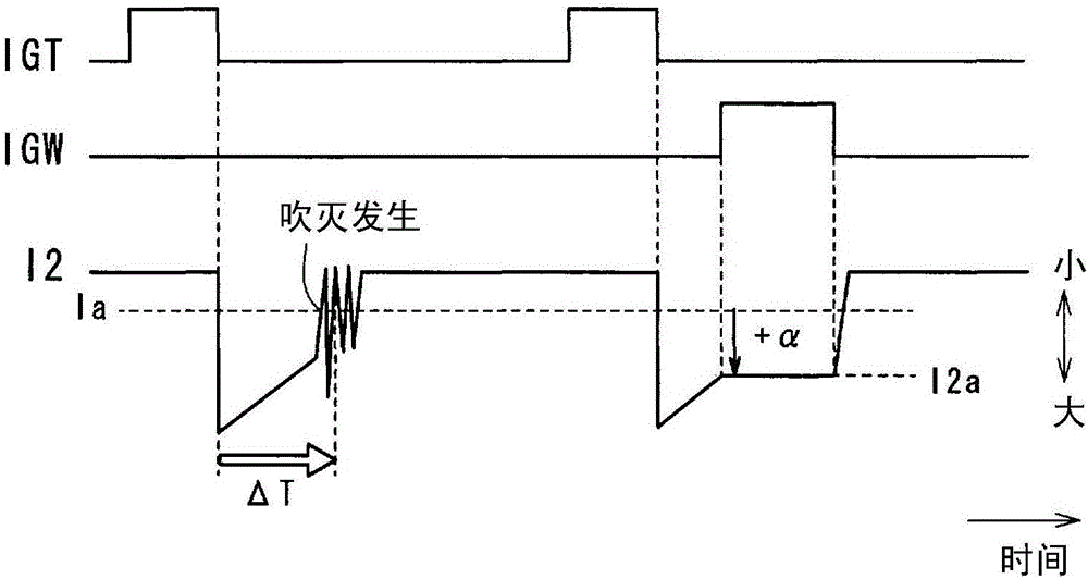
[0097] In the ignition device of the present embodiment, when it is determined that blow-out occurs during the sustain spark discharge, the energy input instruction unit 5a generates the discharge sustain signal IGW to perform the sustain spark discharge in the next cycle, and sets the predetermined threshold value Ia and The current value obtained by adding the predetermined current values ​​α' is set as the secondary current command value in the continuous spark discharge in the next cycle.

[0098] That is, if it is determined that blow-out occurs when the cycle of sustaining spark discharge has already been adopted for the blow-out determination by main ignition, sustain spark discharge is also performed in the next cycle. In addition, the secondary current command value I2a at this time is se...


PUM


Abstract

An ignition device comprising a blow-out determination unit that determines that a blow-out has occurred, if a secondary current has dropped below a prescribed threshold (Ia) during a determination period, said determination period being a prescribed time ([delta]T) from the start of spark discharge by a main ignition circuit. If a determination is made that a blow-out has occurred during main ignition (during full-transistor ignition), the ignition device controls so as to perform continuous spark discharge after main ignition in the next cycle. The secondary current command value (I2a) at this time is set as a current value having a prescribed current value ([alpha]) added to the prescribed threshold (Ia) used for the blow-out determination. As a result, escalation to a misfire can be reliably prevented because blow-out can be reliably prevented in the next cycle.

Description

technical field [0001] The present invention relates to an ignition device used in an internal combustion engine (engine), in particular to a continuous technology of spark discharge. Background technique [0002] In order to reduce the burden of repeatedly blowing out and re-discharging the spark plug, and to suppress unnecessary power consumption and continue spark discharge, the present applicant proposed an energy input circuit (unknown technology). After starting the initial spark discharge (called main ignition) by a well-known ignition circuit, the energy input circuit inputs electric energy from the low voltage side of the primary coil toward the battery voltage supply line before the main ignition is blown out. The current in the same direction (direct current secondary current) continues to flow through the coil, and the spark discharge generated by the main ignition continues for an arbitrary period (hereinafter referred to as the discharge continuation period). ...

Claims


Application Information

Patent Timeline
IPC IPC(8): F02P15/10H01F38/12
CPCF02P3/0442F02P3/0846F02P3/0876F02P5/15F02P9/007F02P17/12F02D2200/101Y02T10/40H01F38/12F02P3/09F02P15/10H01F7/064
Inventor 京田贤太中山觉
Owner DENSO CORP
Learn More