Noise reduction method for noise reduction earphones
A noise-cancelling headphone and noise-cancelling technology, applied in the direction of headphones to reduce environmental noise, earpiece/headphone accessories, etc., can solve the problems of high power consumption of the headphone amplifier circuit and difficulty in external noise, and achieve power reduction, high-precision playback effect, guarantee The effect of the playback effect
- Summary
- Abstract
- Description
- Claims
- Application Information
AI Technical Summary
Problems solved by technology
Method used
Image

Examples
Embodiment 1
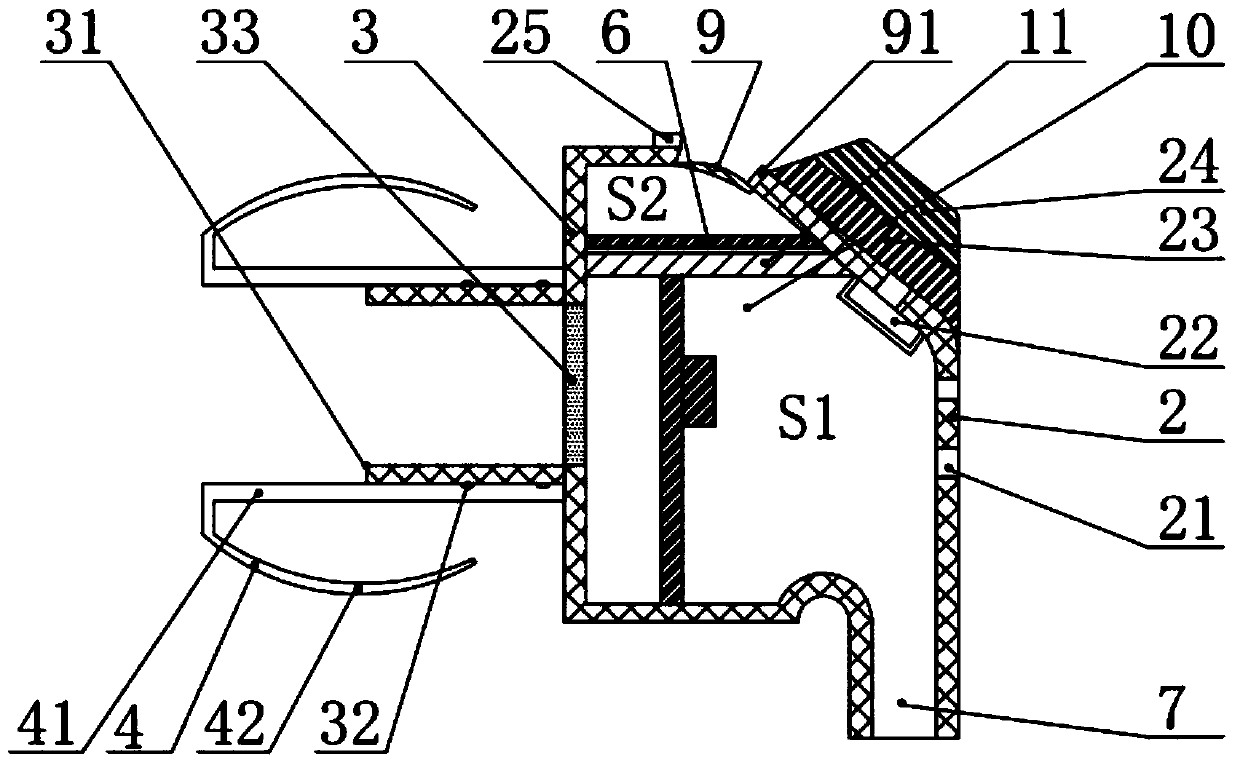
[0023] Such as figure 2 As shown in , in the earphone 10 , a main housing 2 as a main part of the earphone 10 , a front housing 3 , an ear canal tube 31 attached to the front housing, and an earplug 4 are included.
[0024] The ear canal tube 31 is a tubular extension, and the earplug 4 is attached to the ear canal tube 31. In particular, there is an annular protrusion 32 on the outer periphery of the ear canal tube 31. When the earplug 4 is fitted with the ear canal tube 31 , to prevent the earplug nested on the ear canal tube 31 from slipping out easily.
[0025] The earplug 4 has a cylindrical member 41 nested on the ear canal tube 31 , and a spacer member 42 folded back from the front end of the cylindrical member 41 . In particular, the insulating part 42 is formed into a soft hemispherical shape, and after the earplug 4 is inserted into the external auditory canal of the human ear, it can closely contact with the external auditory canal to prevent sound leakage and enh...
Embodiment 2
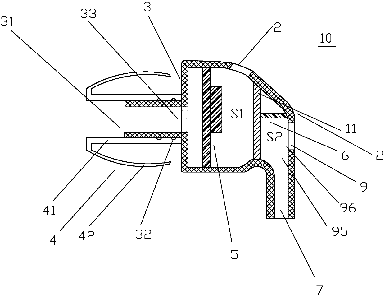
[0039] Such as figure 2 As shown, different from that in Embodiment 1, the first space S1 and the second space S2 are arranged in parallel.
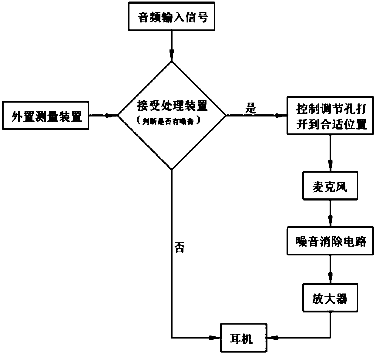
[0040] Alternatively, the door of the adjustment hole 9 can also be realized by means of an electric switch door. The electric switch can be actuated by a tiny piezoelectric element. Specifically, outside the adjustment hole 9 is a fixed baffle, which has many micro-holes; in the adjustment hole, a movable baffle 96 is arranged close to the fixed baffle, and the movable baffle 96 is correspondingly arranged. There are many micro-holes, and the movable baffle can be moved linearly or rotated along a certain direction (such as left or clockwise) on the surface of the fixed baffle, so that the micro-holes of the two baffles are dislocated, and the The non-microporous part blocks the micropores of the fixed baffle. The piezoelectric element 95 is connected with the movable baffle 96 and can directly drive the movable baffle 96 to move. Th...
PUM
 Abstract
Description
Claims
Application Information
 - Generate Ideas
- Intellectual Property
- Life Sciences
- Materials
- Tech Scout
- Unparalleled Data Quality
- Higher Quality Content
- 60% Fewer Hallucinations
Browse by: Latest US Patents, China's latest patents, Technical Efficacy Thesaurus, Application Domain, Technology Topic, Popular Technical Reports.
© 2025 PatSnap. All rights reserved.Legal|Privacy policy|Modern Slavery Act Transparency Statement|Sitemap|About US| Contact US: help@patsnap.com