
Artificial muscle-driven and structurally decoupled robotic joints

A technology of robotic joints and artificial muscles, applied in manipulators, manufacturing tools, program-controlled manipulators, etc., can solve problems such as nonlinear stiffness, low-frequency flutter, and increase the difficulty of control, avoiding interference, high stiffness, and low stiffness. Effect

Active Publication Date: 2018-11-13
ZHEJIANG UNIV OF TECH
View PDF6 Cites 0 Cited by
  • Summary
  • Abstract
  • Description
  • Claims
  • Application Information

AI Technical Summary

Problems solved by technology

For most industrial robots, the main source of deformation is joint deformation, which brings a series of problems: 1) It seriously affects the positioning accuracy and trajectory accuracy of the robot; Severe low-frequency flutter can be found in the process; 3) The introduction of joint flexibility increases the difficulty of control; 4) There are stiffness nonlinearities caused by inconsistent stiffness of internal parts, etc.
In response to the above problems, domestic and foreign scholars such as Bittencourt, Erkaya, Cai Hegao, Yu Yueqing, He Guangping, and Rigatos conducted research from the perspectives of joint friction, joint clearance, joint stiffness identification, flexible joint control, and joint impedance control. , vibration suppression, etc. have obvious promotion effects, but because these researches are mainly carried out around the motor-driven joint construction mode, the above-mentioned problems cannot be fundamentally eliminated. Therefore, solving this problem has become one of the important research topics.

Method used


Image

  • Artificial muscle-driven and structurally decoupled robotic joints
  • Artificial muscle-driven and structurally decoupled robotic joints
  • Artificial muscle-driven and structurally decoupled robotic joints

Examples


Embodiment

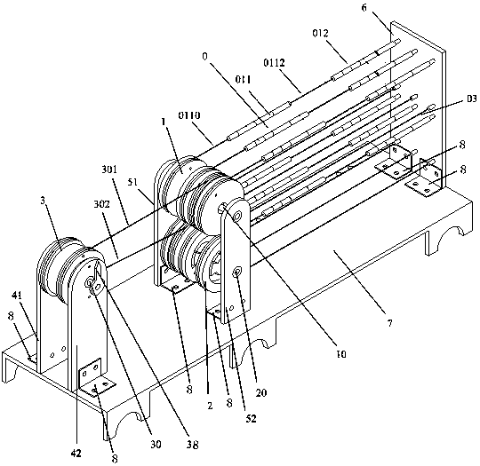
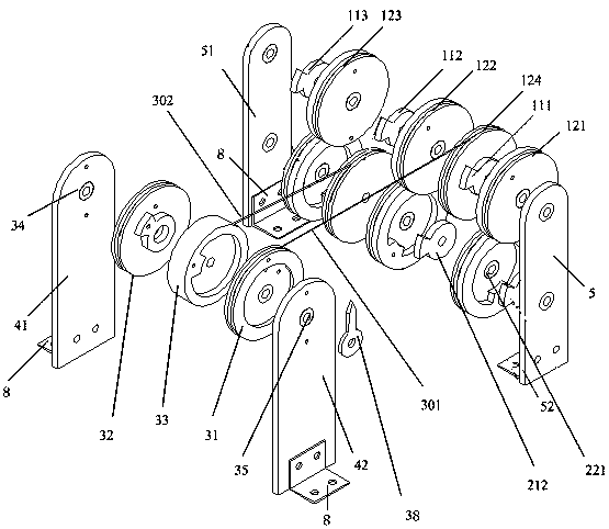
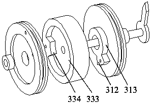
[0030] The present invention adopts the SMA spring as the artificial muscle actuator unit. Since the SMA spring has only two states of contraction and relaxation, in the contraction state, the stiffness is large, and in the relaxation state, the stiffness is small; according to the electrothermal driving characteristics of the SMA spring, by controlling the SMA spring The current of each SMA spring in the spring group is turned on and off to drive the auxiliary joint drive wheel set connected to it, and then drive the main joint drive wheel set to turn a certain angle to realize joint control. The artificial muscle group of the present invention is a series-parallel structure , in this embodiment, it is composed of 12 SMA springs, 6 groups are arranged in parallel and each group is arranged in series, 3 groups of artificial muscles are distributed in each of the two auxiliary joint pulley groups, and the SMA springs are connected by artificial ligament units, as As a special ca...


PUM


Abstract

The invention discloses an artificial muscle driving and structural decoupling robot joint, and belongs to the technical field of robot parts. The robot joint comprises a base, a front vertical plate set, a middle vertical plate set and a rear vertical plate. A main joint pulley block is arranged on the front vertical plate set. A first auxiliary joint pulley block and a second auxiliary joint pulley block are arranged on the middle vertical plate set. One end of a first muscle group traction wire is arranged on the main joint pulley block, and the other end of the first muscle group traction wire is arranged on the first auxiliary joint pulley block. One end of a second muscle group traction wire is arranged on the main joint pulley block, and the other end of the second muscle group traction wire is arranged on the second auxiliary joint pulley block. The end of a main joint shaft of the main joint pulley block is connected with a main joint movement arm. Experiments are conducted by means of different artificial muscle actuator units, an auxiliary joint driving pulley block connected with the robot joint is driven by controlling the on and off of currents of all SMA springs in an SMA spring set according to the electro-thermal driving characteristics of the SMA springs, then a main joint driving pulley block is driven to rotate by a certain degree, joint control is achieved, and the interference problem between all the SMA springs is avoided.

Description

technical field [0001] The invention belongs to the technical field of robot components, and in particular relates to a robot joint driven by artificial muscles and decoupled in structure. Background technique [0002] The robot joint is an important part that affects the dynamic and static characteristics of the robot. For most industrial robots, the main source of deformation is joint deformation, which brings a series of problems: 1) It seriously affects the positioning accuracy and trajectory accuracy of the robot; Severe low-frequency flutter can be found in the process; 3) The introduction of joint flexibility increases the difficulty of control; 4) There are stiffness nonlinearities caused by inconsistent stiffness of internal parts. In response to the above problems, domestic and foreign scholars such as Bittencourt, Erkaya, Cai Hegao, Yu Yueqing, He Guangping, and Rigatos conducted research from the perspectives of joint friction, joint clearance, joint stiffness i...

Claims


Application Information

Patent Timeline
Patent Type & Authority Patents(China)
IPC IPC(8): B25J9/10B25J17/02
CPCB25J9/104B25J9/1075B25J17/0208
Inventor 应申舜鲍官军黄金涛
Owner ZHEJIANG UNIV OF TECH
Learn More