


Quick Research
Generate reliable direction feasibility study reports for your R&D in just a few steps.

Technical Q&A
Discover and master advanced knowledge NOW. Basics, ideas, possibilities, all at once.

Find Solutions
As an expert in R&D theories, this can generate solutions to your technical problems instantly.

Evaluate Feasibility
Analyze your overall solution with one click, know your potential R&D risks in advance.

Monitor Landscape
Get weekly tech updates, stay abreast of the latest tech innovations and key insights.
Polarizing plate, image display and liquid crystal display device
A technology for image display devices and polarizers, applied in polarizing elements, instruments, optics, etc., can solve problems such as air bubbles, and achieve excellent curl resistance
- Summary
- Abstract
- Description
- Claims
- Application Information
AI Technical Summary
Problems solved by technology
Method used
Image

Examples
no. 1 Embodiment approach 〕
[0043] As the first embodiment of the polarizing plate of the present invention, a polarizing plate provided with a polarizer, a protective film, and a peeling film in this order is mentioned. In addition, after bonding a polarizing plate to an adherend, the release film is usually peeled off from the polarizing plate.
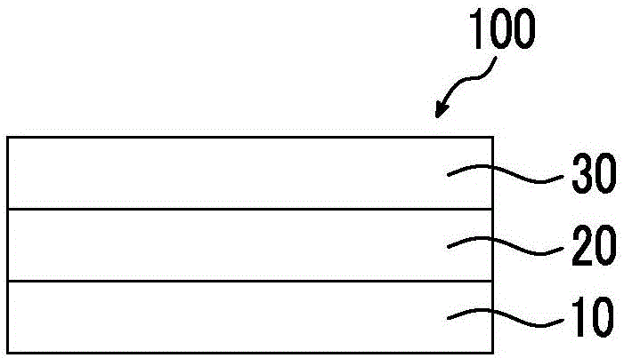
[0044] figure 1 A schematic cross-sectional view of a polarizing plate 100 as a first embodiment of the polarizing plate of the present invention is shown.
[0045] The polarizing plate 100 is provided with the polarizer 10, the protective film 20, and the peeling film 30 in this order.
[0046] Hereinafter, a polarizer, a protective film, and a peeling film are demonstrated.
[0047]
[0048] The polarizer may be any member as long as it has a function of converting light into specific linearly polarized light. For example, an absorption polarizer, a reflective polarizer, or the like can be used.
[0049] As the absorption-type polarizer, an iodine-based...
no. 2 Embodiment approach 〕
[0086] As a second embodiment of the polarizing plate of the present invention, a polarizing plate provided with a polarizer, a protective film, an adhesive layer, and a release film in this order is mentioned. It is preferable that the polarizing plate of the present invention is provided with an adhesive layer between the protective film and the release film, as in the second embodiment, because the release film is stably adhered. Moreover, after bonding a polarizing plate to a to-be-adhered body normally, a peeling film and an adhesive layer are peeled off from a polarizing plate.
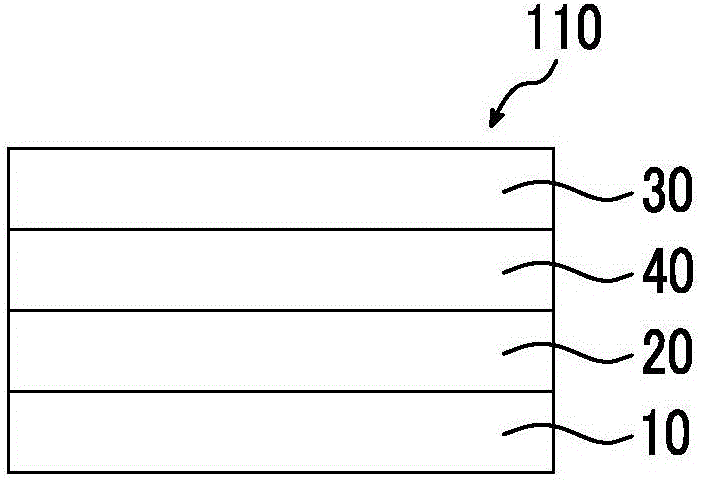
[0087] figure 2 A schematic cross-sectional view of a polarizing plate 110 as a second embodiment of the polarizing plate of the present invention is shown.
[0088] The polarizing plate 110 is provided with the polarizer 10, the protective film 20, the adhesive layer 40, and the release film 30 in this order.
[0089] About a polarizer, a protective film, and a peeling film, it is as above-m...
no. 3 Embodiment approach 〕
[0099] A third embodiment of the polarizing plate of the present invention includes a polarizing plate provided with a polarizer, a protective film, a hard coat layer, an adhesive layer, and a release film in this order. Moreover, after bonding a polarizing plate to a to-be-adhered body normally, a peeling film and an adhesive layer are peeled off from a polarizing plate.
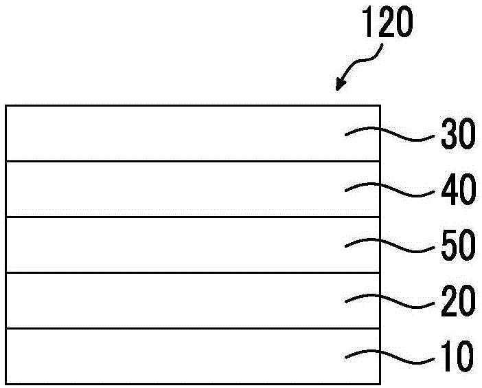
[0100] image 3 A schematic cross-sectional view of a polarizing plate 120 which is a third embodiment of the polarizing plate of the present invention is shown.
[0101] Polarizing plate 120 includes polarizer 10 , protective film 20 , hard coat layer 50 , adhesive layer 40 , and release film 30 in this order.
[0102] The polarizer, protective film, adhesive layer, and release film are as described above.
[0103] Hereinafter, the hard coat layer will be described.
[0104]
[0105] The hard coat layer is a layer mainly used to impart physical strength to the polarizing plate.
[0106] The hard coat...
PUM
| Property | Measurement | Unit |
|---|---|---|
| elastic modulus | aaaaa | aaaaa |
| elastic modulus | aaaaa | aaaaa |
| length | aaaaa | aaaaa |
Abstract
Description
Claims
Application Information
 - R&D Engineer
- R&D Manager
- IP Professional
- Industry Leading Data Capabilities
- Powerful AI technology
- Patent DNA Extraction
Browse by: Latest US Patents, China's latest patents, Technical Efficacy Thesaurus, Application Domain, Technology Topic, Popular Technical Reports.
© 2024 PatSnap. All rights reserved.Legal|Privacy policy|Modern Slavery Act Transparency Statement|Sitemap|About US| Contact US: help@patsnap.com