LED light-emitting lamp filament and LED bulb adopting same
A technology of LED light source and LED chip, applied in electroluminescent light source, semiconductor device of light-emitting element, lampshade, etc., can solve the problems of broken connecting wire, mechanical and thermal shock, LED filament failure, etc., to increase the service life, The effect of avoiding breakage and reducing heat generation
- Summary
- Abstract
- Description
- Claims
- Application Information
AI Technical Summary
Problems solved by technology
Method used
Image
Examples
Embodiment 1
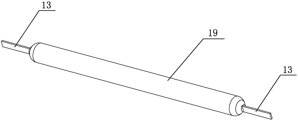
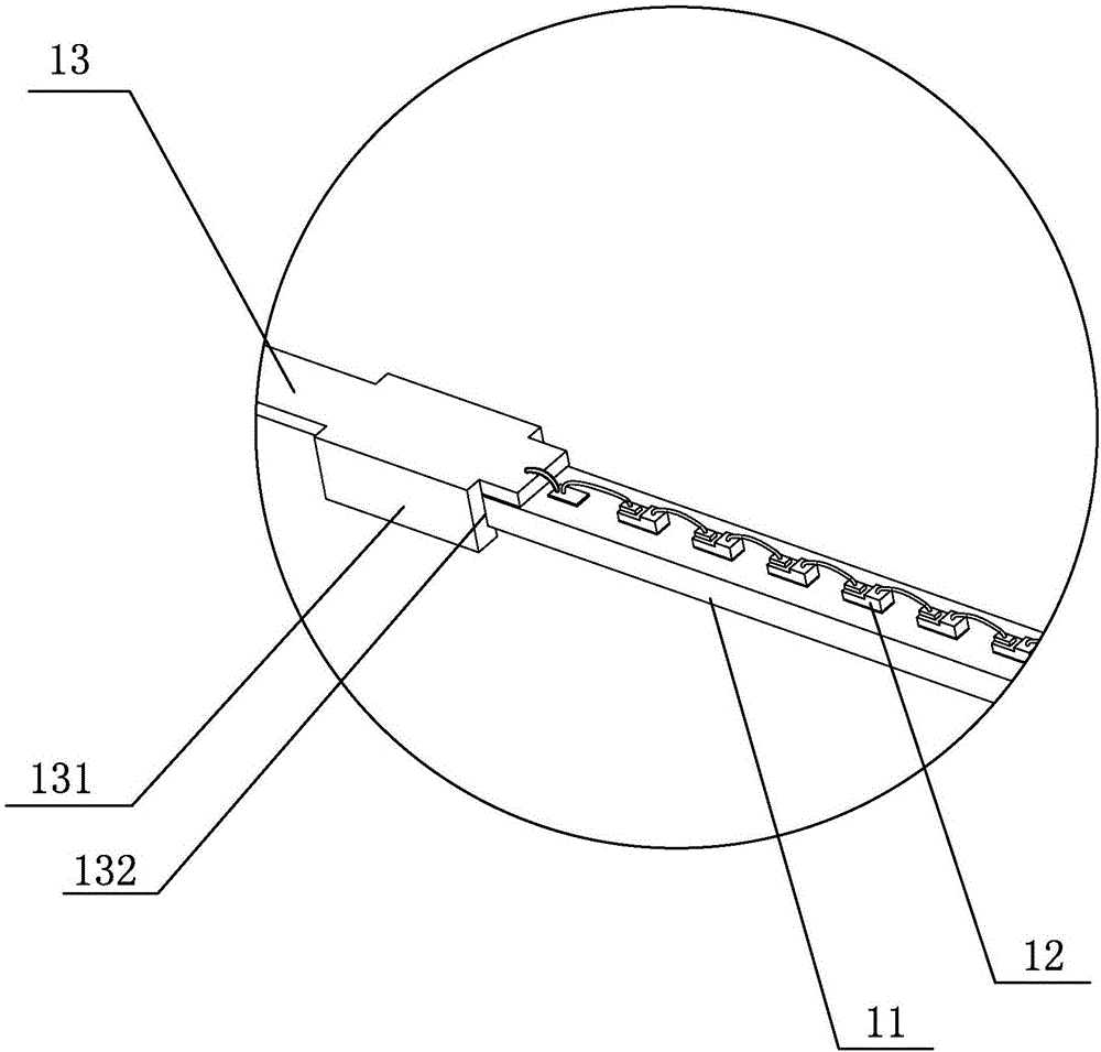
[0035] A kind of LED light-emitting filament that present embodiment proposes, such as Figure 1a to Figure 1c As shown, it includes a strip-shaped substrate 11 and a plurality of LED chips 12 evenly arranged on the strip-shaped substrate 11, a metal strip-shaped electrode 13 is respectively arranged on the two ends of the strip-shaped substrate 11, and a plurality of LED chips 12 Connect in series to form an LED light source. An electronic device with a conductive function is provided on the strip substrate 11 near the two ends. Area, the first conductive block 14 is located between the first metal strip electrode 13 and the LED light source, the second conductive block 14 is located between the LED light source and the second metal strip electrode 13, the first metal strip The electrode 13, the first conductive block 14, the LED light source, the second conductive block 14 and the second metal strip electrode 13 are sequentially connected in series through wires, and the str...
Embodiment 2
[0040] A kind of LED light-emitting filament that present embodiment proposes, such as Figure 2a As shown, it includes a strip-shaped substrate 11 and a plurality of LED chips 12 evenly arranged on the strip-shaped substrate 11. A metal strip-shaped electrode 13 is respectively arranged on the two ends of the strip-shaped substrate 11, and a plurality of LED chips 12 Connected in series to form an LED light source, an electronic device with a protective function is provided on the strip substrate 11 near one of the ends, the electronic device is a varistor 15, and the varistor 15 is located on one of the metal strip electrodes 13 and the LED light source, one of the metal strip electrodes 13, the LED light source and the other metal strip electrode 13 are sequentially connected in series through wires, the piezoresistor 15 and an LED chip 12 are connected in parallel through wires, and the strip substrate 11 , LED light source, piezoresistor 15 and strip substrate 11 and the ...
Embodiment 3
[0045] A kind of LED light-emitting filament that present embodiment proposes, such as Figure 3a As shown, it includes a strip-shaped substrate 11 and a plurality of LED chips 12 evenly arranged on the strip-shaped substrate 11, a metal strip-shaped electrode 13 is respectively arranged on the two ends of the strip-shaped substrate 11, and a plurality of LED chips 12 Connect in series to form an LED light source. An electronic device with a current limiting function is provided on the strip substrate 11 near one of the ends. The electronic device is a current limiting chip 16, and the current limiting chip 16 is located on one of the metal strip electrodes. 13 and the LED light source, one of the metal strip electrodes 13, the current limiting chip 16, the LED light source and the other metal strip electrode 13 are sequentially connected in series through wires, the strip substrate 11, the LED light source, and the current limiting chip 16 And the periphery of the connection ...
PUM
| Property | Measurement | Unit |
|---|---|---|
| diameter | aaaaa | aaaaa |
| diameter | aaaaa | aaaaa |
Abstract
Description
Claims
Application Information
 - R&D
- Intellectual Property
- Life Sciences
- Materials
- Tech Scout
- Unparalleled Data Quality
- Higher Quality Content
- 60% Fewer Hallucinations
Browse by: Latest US Patents, China's latest patents, Technical Efficacy Thesaurus, Application Domain, Technology Topic, Popular Technical Reports.
© 2025 PatSnap. All rights reserved.Legal|Privacy policy|Modern Slavery Act Transparency Statement|Sitemap|About US| Contact US: help@patsnap.com


