
Five-degree-of-freedom outer rotor permanent magnet bias spherical magnetic bearing

A technology of permanent magnetic bias and external rotor, which is applied in the direction of bearings, shafts and bearings, mechanical equipment, etc., can solve the problems of not considering the axial control, difficulty in meeting the application occasions, reducing the control accuracy of the rotor, etc., and achieve power consumption Low, simple structure, and the effect of increasing the number of degrees of freedom

Inactive Publication Date: 2016-11-23
JIANGSU UNIV
View PDF8 Cites 7 Cited by
  • Summary
  • Abstract
  • Description
  • Claims
  • Application Information

AI Technical Summary

Problems solved by technology

[0004] Chinese patent application number 201510029481.3 proposes an outer rotor spherical radial pure electromagnetic bearing, which uses a bias current to generate a bias magnetic field, which consumes a lot of power, is complex to control, and has insufficient degrees of freedom. Control the axial direction, so it is difficult to meet some special applications
When the inertial axis of the rotor deviates from the geometric axis, the magnitude of the electromagnetic force in each magnetic pole surface is not equal, and all of them do not exceed the center of mass, which will cause radial torsion interference torque to the rotor, forcing the rotor to drift and reducing the control accuracy of the rotor.

Method used


Image

  • Five-degree-of-freedom outer rotor permanent magnet bias spherical magnetic bearing
  • Five-degree-of-freedom outer rotor permanent magnet bias spherical magnetic bearing
  • Five-degree-of-freedom outer rotor permanent magnet bias spherical magnetic bearing

Examples


Embodiment Construction

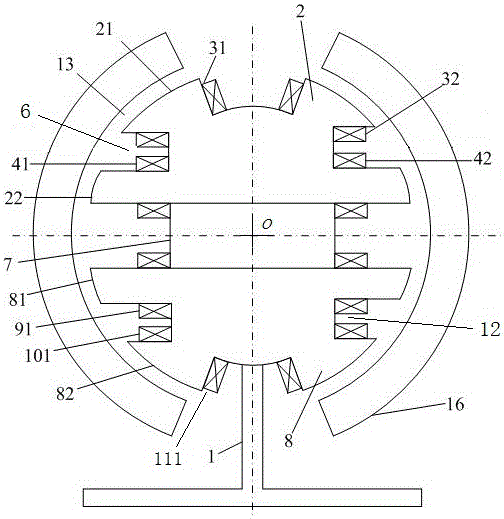
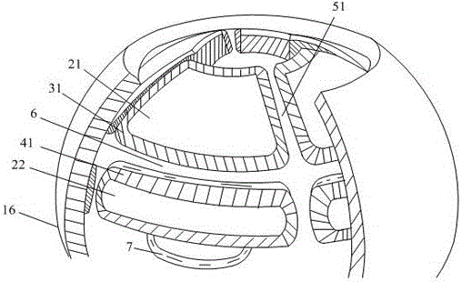
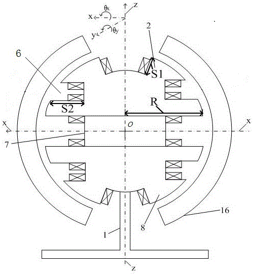
[0023] Such as figure 1 As shown, the present invention consists of a rotating shaft 1, two stators, a permanent magnet 7, a rotor 16 and control coils. The rotor 16 is spherical, and a permanent magnet 7 and two stators are located in the center of the rotor 16. The upper and lower parts of the rotor 16 each have an opening. The longitudinal shaft 1 extends into the rotor 16 from the lower opening of the rotor 16 and passes through a permanent magnet. 7 and the longitudinal through hole in the middle of the two stators, a permanent magnet 7 and the two stators are all empty sleeves on the rotating shaft 1. The central axes of the upper and lower openings on the rotor 16, the central axes of a permanent magnet 7 and the two stators coincide with the central axes of the rotating shaft 1, and all pass through the center of the rotor 16 o .

[0024] The two stators are respectively an upper stator 2 and a lower stator 8, both of which are hemispherical and have identical struct...


PUM


Abstract

The invention discloses a five-degree-of-freedom outer rotor permanent magnet bias spherical magnetic bearing. The five-degree-of-freedom outer rotor permanent magnet bias spherical magnetic bearing comprises a spherical rotor. Two stators and a permanent magnet are arranged in the center in the rotor. The upper stator and the lower stator are located on the upper side and the lower side of the permanent magnet in a mirror symmetry manner. The upper stator and the lower stator are the same in structure and are in a semispherical shape, and the permanent magnet is cylindrical. An upper axial groove is formed in the outer surface of the upper stator at every 90-degree internal in the circumferential direction. An upper annular radial groove is formed in the outer surface of the axial middle of the upper stator in the circumferential direction. The upper annular radial groove and the four upper axial grooves are through and intersect with one another, and four stator magnetic poles are formed in an upper-lower layer manner. The lower stator is also provided with four lower axial grooves and a lower annular radial groove, and four stator magnetic poles of the lower stator are formed in an upper-lower layer manner, and a control coil is wound around each magnetic pole; and the control current of the magnetic bearing can be reduced, the power amplifier loss is lowered, and the size of the magnetic bearings is reduced.

Description

technical field [0001] The invention relates to a non-mechanical contact spherical magnetic bearing, in particular to a five-degree-of-freedom outer rotor permanent magnet bias spherical magnetic bearing, which can be used as a magnetic levitation gyroscope, a magnetic levitation molecular pump, a magnetic levitation momentum wheel, etc. requiring high-speed and high-precision control , non-contact suspension support for clean, pollution-free, and long-life mechanical equipment. Background technique [0002] Magnetic suspension bearings are divided into pure electromagnetic bearings and permanent magnetic bias hybrid magnetic bearings. The former uses bias current to generate a bias magnetic field, and uses the control magnetic field generated by the control current to adjust the magnitude of the electromagnetic force. It has two controllable magnetic fields. The latter utilizes a permanent magnet to provide a bias magnetic field, and an electromagnetic field to provide an a...

Claims


Application Information

Patent Timeline
Patent Type & Authority Applications(China)
IPC IPC(8): F16C32/04
CPCF16C32/0421
Inventor 张维煜陈涛朱熀秋
Owner JIANGSU UNIV
Learn More