Compressor crankshaft oiling structure, compressor oil way structure and compressor

A compressor crankshaft and compressor technology, which is applied in the field of compressors, can solve problems such as difficult processing of crankshaft oblique oil holes, and achieve the effects of easy detection and measurement, reduced processing costs, and easy control

Inactive Publication Date: 2016-11-23
ZHUHAI GREE REFRIGERATION TECH CENT OF ENERGY SAVING & ENVIRONMENTAL PROTECTION
View PDF6 Cites 0 Cited by
  • Summary
  • Abstract
  • Description
  • Claims
  • Application Information

AI Technical Summary

Problems solved by technology

[0005] One of the purposes of the present invention is to propose a compressor crankshaft oiling structure, which solves the problem of difficult machining of the inclined oil hole of the crankshaft, reduces the processing steps, reduces...

Method used


Image

  • Compressor crankshaft oiling structure, compressor oil way structure and compressor
  • Compressor crankshaft oiling structure, compressor oil way structure and compressor
  • Compressor crankshaft oiling structure, compressor oil way structure and compressor

Examples


Embodiment Construction

[0028] In order to make the technical problems solved by the present invention, the technical solutions adopted and the technical effects achieved clearer, the technical solutions of the embodiments of the present invention will be further described in detail below in conjunction with the accompanying drawings. Obviously, the described embodiments are only the technical solutions of the present invention. Some implementations, not all implementations. Based on the implementation manners in the present invention, all other implementation manners obtained by those skilled in the art without creative efforts fall within the protection scope of the present invention.

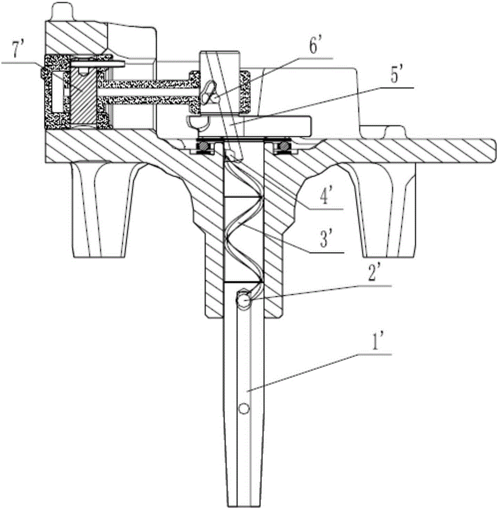
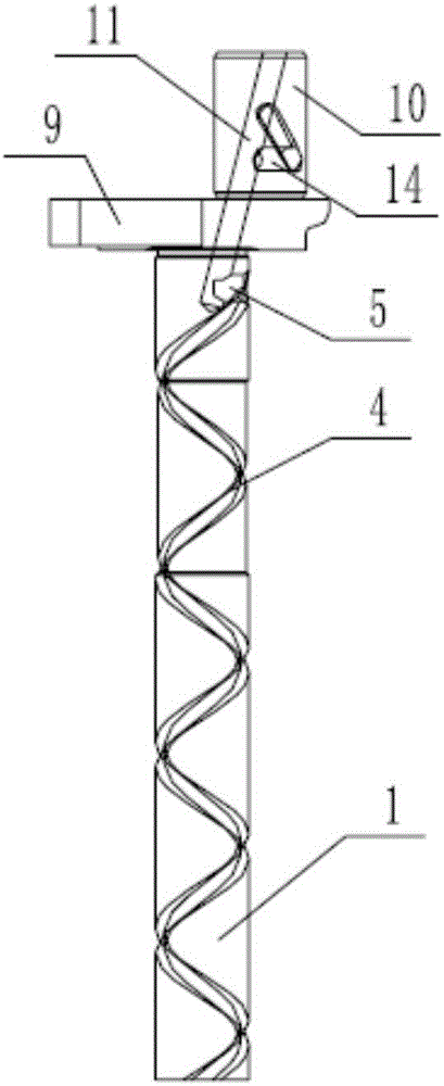
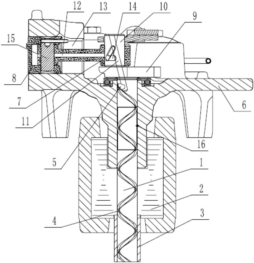
[0029] see figure 2 with image 3 , this embodiment proposes an oiling structure for the crankshaft of the compressor, including the main shaft 1 of the crankshaft, the rotor 2 and the bushing 3 connected to the crankshaft, and the surface of the main shaft 1 is provided with an oil supply passage 4 running throug...


PUM


Abstract

The invention discloses an oiling structure for a compressor crankshaft, which relates to the technical field of compressors. The crankshaft oiling structure of the compressor includes the main shaft of the crankshaft and the rotor connected to the crankshaft. The surface of the main shaft is provided with an oil supply passage through its axial direction; it also includes a shaft sleeve installed on the shaft of the rotor. In the hole, and sleeved on the lower end of the main shaft, an oil supply passage is formed between the main shaft, the sleeve and the rotor. At the same time, it also discloses a compressor oil circuit structure and a compressor with the above compressor crankshaft oiling structure. The invention solves the problem of difficult machining of the inclined oil hole of the crankshaft, reduces the processing steps, reduces the processing cost of the product, and reduces the risk of blockage of the oil passage caused by burrs caused by improper drilling and processing of the crankshaft. quality control.

Description

technical field [0001] The invention relates to the technical field of compressors, in particular to a compressor crankshaft oiling structure, a compressor oil circuit structure and a compressor having the compressor crankshaft oiling structure. Background technique [0002] Currently, if figure 1 As shown, the crankshaft oil circuit structure generally adopted by piston compressors with small diameter crankshafts is as follows: through the centrifugal force of the crankshaft rotation, the lubricating oil enters the crankshaft along the oil inclined hole 1' on the lower end of the crankshaft, passes through the main shaft lubricating oil hole 2', and the main shaft lubricating oil The oil hole 4' and the helical oil groove 3' are oiled to lubricate the crankshaft main shaft. The part from the main shaft of the crankshaft to the crank is lubricated through the inclined hole 5' leading to the top of the crankshaft. After the lubricating oil reaches the crankshaft, part of it ...

Claims


Application Information

Patent Timeline
IPC IPC(8): F04B39/00F04B39/02
CPCF04B39/0094F04B39/02
Inventor 曹政徐敏
Owner ZHUHAI GREE REFRIGERATION TECH CENT OF ENERGY SAVING & ENVIRONMENTAL PROTECTION
Why Eureka
Try Eureka