
Device for separately refluxing nitrifying liquid and sludge

A backflow device and nitrifying solution technology, applied in water/sludge/sewage treatment, chemical instruments and methods, biological water/sewage treatment, etc. Effect

Pending Publication Date: 2016-11-23
HUAYI ENVIRONMENTAL PROTECTION CO LTD
View PDF8 Cites 3 Cited by
  • Summary
  • Abstract
  • Description
  • Claims
  • Application Information

AI Technical Summary

Problems solved by technology

[0005] The technical problem to be solved by the present invention is to overcome the phenomenon that the simple nitrification liquid sludge return device in the prior art will lead to the inhibition of phosphorus release by phosphorus accumulating bacteria in the anaerobic zone

Method used


Image

  • Device for separately refluxing nitrifying liquid and sludge
  • Device for separately refluxing nitrifying liquid and sludge

Examples


Embodiment 1

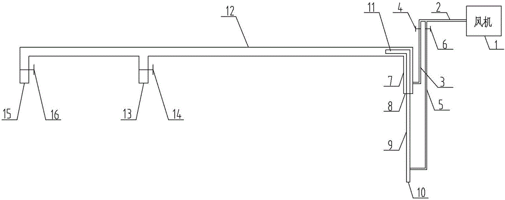
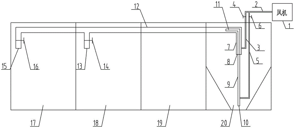
[0027] figure 1 Shown is a specific embodiment of the nitrifying liquid sludge return device respectively, the device mainly includes a nitrifying liquid riser 7 and a sludge riser 9, wherein the nitrifying liquid riser 7 and the sludge riser 9 are vertically inserted into the In the settling area 20, and the nitrification liquid riser sleeve 7 is arranged on the outside of the sludge riser 9; the nitrification liquid riser 7 has a liquid lift section extending from top to bottom to the supernatant position of the biochemical tank sedimentation area 20, And the pumping device for sucking the nitrifying liquid from the nitrifying liquid lifting pipe water inlet 8 of the liquid lifting section; the sludge lifting pipe 9 has a mud lifting section stretching from top to bottom to the bottom of the sedimentation zone 20, and lifts from the mud A sludge pumping device for sucking sludge through the sludge lifter inlet 10 of the sludge lifter section, wherein the sludge lifter inlet ...


PUM


Abstract

The invention relates to a device for separately refluxing nitrifying liquid and sludge. The device comprises a nitrifying liquid riser and a sludge riser, wherein the nitrifying liquid riser is provided with a liquid riser section which extends into a position of supernatant of a precipitation area from top to bottom, and a liquid pumping device used for pumping the nitrifying liquid from a liquid inlet of the liquid riser section; the sludge riser is provided with a sludge riser section which extends into the bottom of the precipitation area from top to bottom, and a sludge pumping device used for pumping the sludge from a sludge inlet of the sludge riser section; the position of the sludge inlet of the sludge riser section is lower than that of the liquid inlet of the liquid riser section, and the sludge riser section extends into the precipitated sludge; the nitrifying liquid riser sleeves the outer side of the sludge riser. The invention utilizes one set of equipment to separately realize the refluxing of the nitrifying liquid and the sludge, thus being more integrated, more convenient and faster; furthermore, the device reduces the influence of nitric nitrogen on the biochemical functions of an anaerobic zone.

Description

technical field [0001] The invention relates to the technical field of integrated sewage treatment, in particular to a separate reflux device for nitrifying liquid sludge. Background technique [0002] In integrated sewage treatment equipment, the A2 / O process is a relatively common process. In the anaerobic zone, anaerobic bacteria decompose macromolecular refractory organic matter into easily degradable organic matter, and phosphorus accumulating bacteria release phosphorus in cells in anaerobic environment; in anoxic zone, denitrifying bacteria reduce nitrate nitrogen to Nitrogen to remove total nitrogen; in the aerobic zone, nitrifying bacteria oxidize ammonia nitrogen to nitrate nitrogen, phosphorus accumulating bacteria absorb excessive phosphorus in water in an aerobic environment, and aerobic bacteria decompose remaining BOD, so that the quality of effluent water reaches Require. [0003] In the A2 / O process, the two parts of nitrification liquid return and sludge ...

Claims


Application Information

Patent Timeline
Patent Type & Authority Applications(China)
IPC IPC(8): C02F3/30
CPCC02F3/30C02F3/302
Inventor 侯银顺全盈盈
Owner HUAYI ENVIRONMENTAL PROTECTION CO LTD
Learn More