
Base station and signal transmission method based on spectrum sensing technology

A spectrum sensing and signal transmission technology, applied in wireless communication, transmission monitoring, network planning and other directions, can solve the problems of large-scale, unified promotion, difficult to obtain unified authorized frequency points, and complex communication terminal channel environment that are not suitable for wireless communication systems. , to achieve the effect of improving system reliability, avoiding interference, and avoiding interference

Inactive Publication Date: 2016-11-16
BEIJING HUITONG JINCAI INFORMATION TECH +4
View PDF3 Cites 10 Cited by
  • Summary
  • Abstract
  • Description
  • Claims
  • Application Information

AI Technical Summary

Problems solved by technology

[0003] At present, there are several power wireless communication systems in China. The communication protocols of traditional 230MHz digital transmission stations and Mobitex are simple, and it is difficult to guarantee the spectrum utilization rate; the communication protocols of WiMAX, McWill, and TD-LTE are perfect, but the network structure is complex and the High power consumption, especially difficult to obtain a unified authorized frequency point, not suitable for large-scale and unified promotion of industrial wireless communication systems
In the allocation of existing wireless spectrum resources in China, the spectrum allocated to power users for load monitoring is 40 discrete frequency points within the 223MHz-235MHz frequency band, with a total bandwidth of 1MHz. The frequency point is used for business data transmission, so the channel environment for communication terminals in the power 230MHz frequency band is complex, and there is not only adjacent channel interference from other industry user data transmission stations, but also in-band interference from power user load-controlled data transmission stations

Method used


Image

  • Base station and signal transmission method based on spectrum sensing technology
  • Base station and signal transmission method based on spectrum sensing technology
  • Base station and signal transmission method based on spectrum sensing technology

Examples


Embodiment Construction

[0032] Embodiments of the present invention are described in detail below, examples of which are shown in the drawings, wherein the same or similar reference numerals designate the same or similar elements or elements having the same or similar functions throughout. The embodiments described below by referring to the figures are exemplary only for explaining the present invention and should not be construed as limiting the present invention.

[0033] Those skilled in the art will understand that unless otherwise stated, the singular forms "a", "an", "said" and "the" used herein may also include plural forms. It should be further understood that the word "comprising" used in the description of the present invention refers to the presence of said features, integers, steps, operations, elements and / or components, but does not exclude the presence or addition of one or more other features, Integers, steps, operations, elements, components, and / or groups thereof. It will be unders...


PUM


Abstract

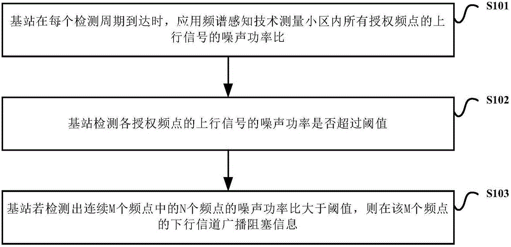
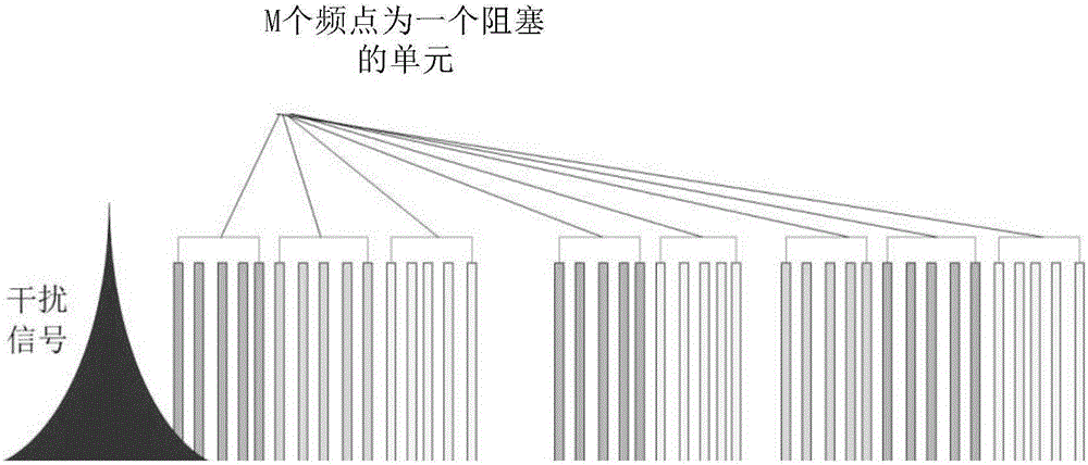
The embodiment of the invention provides a base station and a signal transmission method based on spectrum sensing technology. The method comprises the steps that each base station applies the spectrum sensing technology to measure noise power ratios of uplink signals of all authorized frequency points within a measurement cell when each detection period reaches; if it is detected that the noise power ratios of N frequency points in continuous M frequency points are greater than a threshold, the base station broadcasts blocking information on downlink channels of the M frequency points for indicating the terminal that the transmission frequency points of the blocking information send a pause signal; and then, the base station pauses the transmission of the signals of the M frequency points. By adopting the base station and the signal transmission method provided by the invention, the utilization rate of spectrum resources of a wireless communication system of the industry can be improved, the interference frequency band is evaded to guarantee the communication quality, and the reliability of the system is improved.

Description

technical field [0001] The present invention relates to the field of radio technology, in particular to a base station and a signal sending method based on spectrum sensing technology. Background technique [0002] With the rapid development of wireless technology, mobile high-speed data networks, wireless multimedia applications and other wireless applications with high data rate requirements have been widely deployed, and the number of wireless users is growing explosively, which puts forward new requirements for wireless spectrum. As a country's scarce and non-renewable strategic resources, wireless spectrum resources are uniformly allocated by the relevant management departments of various countries, and all walks of life carry out business applications in the authorized spectrum. Once the spectrum resources are authorized and allocated, it indicates that the wireless resources available for the business are fixed. Facing the new demands of new services and new technolog...

Claims


Application Information

Patent Timeline
Patent Type & Authority Applications(China)
IPC IPC(8): H04W16/10H04B17/382
CPCH04B17/382H04W16/10
Inventor 何清素欧清海蒋梨花贺金红丁佳任玲玲曾令康高德荃
Owner BEIJING HUITONG JINCAI INFORMATION TECH
Learn More