
Vortex electromagnetic wave generation device and method

A vortex electromagnetic wave and generation device technology, applied in electromagnetic wave transmission systems, electrical components, digital transmission systems, etc., can solve problems such as difficulty in OAM mode generation and detection, difficulty in redefining mode topology loads, etc.

Active Publication Date: 2016-11-16
SHANGHAI INST OF MICROSYSTEM & INFORMATION TECH CHINESE ACAD OF SCI
View PDF3 Cites 26 Cited by
  • Summary
  • Abstract
  • Description
  • Claims
  • Application Information

AI Technical Summary

Problems solved by technology

The common limitation of the above methods is that after the design and processing of the antenna or converter is completed, only one or several fixed OAM modes can be generated, and the mode topology cannot be redefined by software.
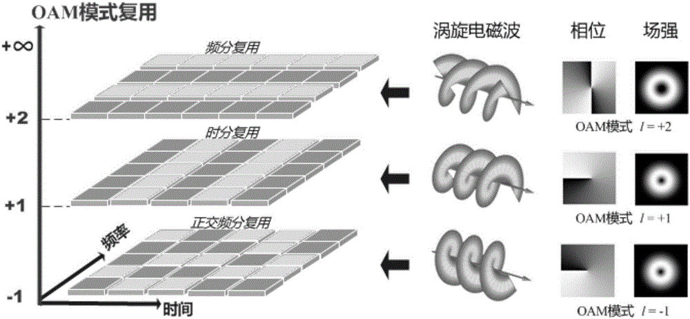
[0006] Orbital angular momentum multiplexing transmission, the research progress in the field of optical communication is exciting (the transmission rate has exceeded 100Tbps); however, in the microwave frequency band most commonly used in wireless communication systems, this technology is still in the stage of theoretical exploration and concept verification. One of the main technical bottlenecks is the above-mentioned "antenna commonality problem of multiple OAM modes"
Due to the inability to use optical devices such as gratings, Q-disks, and phase plates for mode conversion, the generation and detection of OAM modes in the microwave frequency band is more difficult, depending on the special customized design of the transceiver antenna, usually a pair of antennas can only achieve one or a few Several orthogonal modes, it is difficult to use a hardware platform to fully support various OAM modes, so the flexibility and adaptability of the system are limited

Method used


Image

  • Vortex electromagnetic wave generation device and method
  • Vortex electromagnetic wave generation device and method
  • Vortex electromagnetic wave generation device and method

Examples


Embodiment Construction

[0039] Below in conjunction with the drawings, preferred embodiments of the present invention are given and described in detail.

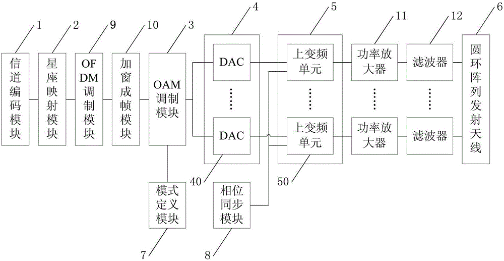
[0040] Such as figure 2 As shown, one of the present invention, namely a kind of vortex electromagnetic wave generating device, comprises: the channel coding module 1 that connects successively, constellation mapping module 2, orbital angular momentum modulation module (hereinafter referred to as OAM modulation module) 3, digital-to-analog conversion Module (hereinafter referred to as DAC module) 4, quadrature up-conversion module 5 and circular array transmitting antenna 6, and the mode definition module 7 connected with OAM modulation module 3, the phase synchronization module 8 connected with quadrature up-conversion module 5 ,in:

[0041] The channel encoding module 1 is used to encode the binary information bit stream input from the periphery;

[0042] Constellation mapping module 2 is used to generate a complex digital signal stream a(n) a...


PUM


Abstract

The invention relates to a vortex electromagnetic wave generation device and method. The device comprises a channel coding module; a constellation mapping module which generates a complex digital signal stream a (n) according to coding information output by the channel coding module; an orbital angular momentum modulation module which converts the complex digital signal stream a (n) into an N-dimensional array element excitation signal B (n) according to a preset OAM (Orbital Angular Momentum) topology charge 1 in a mode definition module, wherein the N-dimensional array element excitation signal B (n) is used for exciting a vortex electromagnetic wave carrying the OAM topology charge 1; a DAC module which carries out digital-to-analogue conversion on the N-dimensional array element excitation signal B (n) and generates an N-dimensional simulation signal C (t); an orthogonal upper conversion module which carries out orthogonal upper conversion on the N-dimensional simulation signal C (t) according to a local oscillation signal directly provided or triggered by a phase synchronization module and generating an N-dimensional radio frequency signal D (t); and a ring array transmitting antenna which is connected with the orthogonal upper conversion module. According to the method and the device, the vortex electromagnetic wave carrying the software-defined OAM topology charge is generated.

Description

technical field [0001] The present invention relates to wireless communication technology, in particular to a device and method for generating vortex electromagnetic waves based on vector modulation. Background technique [0002] According to quantum mechanics and Maxwell's theory, the electromagnetic waves radiated by antennas have wave-particle duality, and can carry linear momentum and angular momentum like moving particles. Electromagnetic wave angular momentum includes two parts: spin angular momentum (SpinAngular Momentum, SAM) and orbital angular momentum (Orbital Angular Momentum, OAM). Among them, SAM is related to photon rotation, which is manifested as left-handed or right-handed circular polarization of electromagnetic waves. ± ( Represents the reduced Planck constant) two orthogonal states; OAM is related to the spatial distribution of the photon wave function, which is the basic property of all "vortex electromagnetic waves", which is manifested by the beam...

Claims


Application Information

Patent Timeline
Patent Type & Authority Applications(China)
IPC IPC(8): H04B10/516H04L1/00
CPCH04B10/516H04L1/0041H04L1/0056H04L1/0076
Inventor 周斌俞凯卜智勇
Owner SHANGHAI INST OF MICROSYSTEM & INFORMATION TECH CHINESE ACAD OF SCI
Learn More