Coordination enhanced transmission method for beam communication
A transmission method and beam technology, applied in the field of cooperative enhanced transmission, can solve problems such as edge UE performance degradation, and achieve the effects of easy coordination, simple implementation, and avoiding low service efficiency
- Summary
- Abstract
- Description
- Claims
- Application Information
AI Technical Summary
Problems solved by technology
Method used
Image

Examples
Embodiment 1
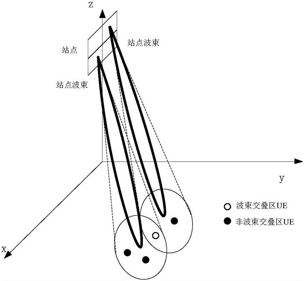
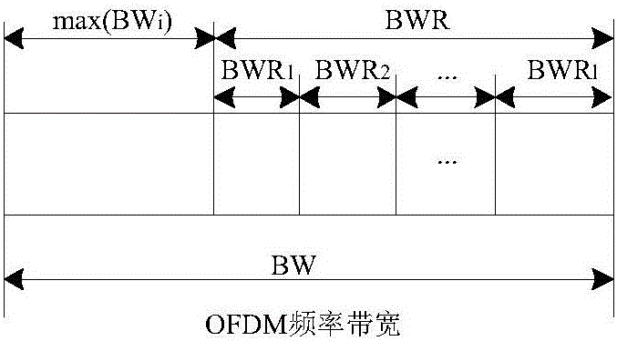
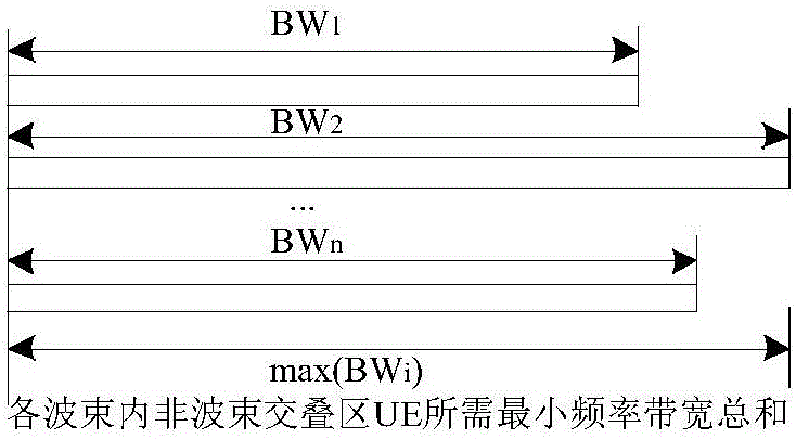
[0044] Example scenarios such as image 3 As shown, in the cell of the cellular network, the UE uses an omnidirectional antenna, and the UE 11 、UE 12 with UE 21 UEs in non-beam overlapping areas of BS beam 1 and beam 2 respectively. UE 1 Located in the overlapping area of two beams, served by BS beam 1 and beam 2, the total frequency resource bandwidth of the system is BW.
[0045] Step 1: When the BS has data to send to the UE, the station initiates a transmission request, and after the UE agrees, the BS beam resource 1 is associated with the user UE to be served 11 、UE 12 、UE 1 , beam resource 2 is associated to the user UE to be served 21 、UE 1 , establish a transmission link, and go to step 2; when the UE has data to send to the BS, the UE initiates a transmission request, and after the station agrees, the BS beam resource 1 is associated with the user UE to be served 11 、UE 12 、UE 1 , beam resource 2 is associated to the user UE to be served 21 、UE 1 , esta...
Embodiment 2
[0053] Example scenarios such as Figure 5 As shown, in the cell of the cellular network, the UE uses an array antenna, and the UE 1 、UE 2 UEs in non-beam overlapping areas of BS beam 1 and beam 2 respectively. UE 3 Located in the overlapping area of two beams, served by BS beam 1 and beam 2, the total frequency resource bandwidth of the system is BW.
[0054] Step 1: When the BS has data to send to the UE, the station initiates a transmission request, and after the UE agrees, the BS beam resource 1 is associated with the user UE to be served 1 、UE 3 , beam resource 2 is associated to the user UE to be served 2 、UE 3 , establish a transmission link, and turn to step 2;
[0055] When the UE has data to send to the BS, the UE initiates a transmission request, and after the station agrees, the BS beam resource 1 is associated with the user UE to be served 1 、UE 3 , beam resource 2 is associated to the user UE to be served 2 、UE 3 , establish a transmission link, and ...
Embodiment 3
[0063] Example scenarios such as Figure 7 As shown, in the cell of the cellular network, the UE uses an omnidirectional antenna, and the UE 1 、UE 2 UEs in non-beam overlapping areas of BS beam 1 and beam 2 respectively. UE 3 with UE 4 Located in the overlapping area of two beams, served by BS beam 1 and beam 2, the total frequency resource bandwidth of the system is BW.
[0064] Step 1: When the BS has data to send to the UE, the station initiates a transmission request, and after the UE agrees, the BS beam resource 1 is associated with the user UE to be served 1 、UE 3 、UE 4 , beam resource 2 is associated to the user UE to be served 2 、UE 3 、UE 4 , establish a transmission link, and go to step 2; when the UE has data to send to the BS, the UE initiates a transmission request, and after the station agrees, the BS beam resource 1 is associated with the user UE to be served 1 、UE 3 、UE 4 , beam resource 2 is associated to the user UE to be served 2 、UE 3 、UE 4 ...
PUM
 Abstract
Description
Claims
Application Information
 - Generate Ideas
- Intellectual Property
- Life Sciences
- Materials
- Tech Scout
- Unparalleled Data Quality
- Higher Quality Content
- 60% Fewer Hallucinations
Browse by: Latest US Patents, China's latest patents, Technical Efficacy Thesaurus, Application Domain, Technology Topic, Popular Technical Reports.
© 2025 PatSnap. All rights reserved.Legal|Privacy policy|Modern Slavery Act Transparency Statement|Sitemap|About US| Contact US: help@patsnap.com