
Chip resistor impedance and standing-wave ratio frequency characteristic measuring device and method

A technology for measuring devices and resistors, which is applied in the field of radio frequency microwaves, can solve the problems of insufficient connection compactness between microwave measuring fixtures and chip resistors, high precision requirements for microwave fixture components, and high manufacturing process requirements, so as to achieve reliable measurement results and reduce The effect of parasitic inductance and accurate input impedance

Inactive Publication Date: 2016-11-16
GUANGDONG UNIV OF TECH
View PDF5 Cites 1 Cited by
  • Summary
  • Abstract
  • Description
  • Claims
  • Application Information

AI Technical Summary

Problems solved by technology

The main disadvantage of this approach is that the data obtained from the equivalent circuit diagram and 3D modeling simulation are approximate results, which are suitable as reference data
[0008] 2. The components of this microwave fixture require high precision, the manufacturing process is very demanding, and the manufacturing cost is very expensive
[0009] 3. The compactness of the connection between the microwave measuring fixture and the chip resistor is also a shortcoming. It is better to solder the chip resistor directly to the circuit board to make it more closely connected.

Method used


Image

  • Chip resistor impedance and standing-wave ratio frequency characteristic measuring device and method
  • Chip resistor impedance and standing-wave ratio frequency characteristic measuring device and method
  • Chip resistor impedance and standing-wave ratio frequency characteristic measuring device and method

Examples


Embodiment

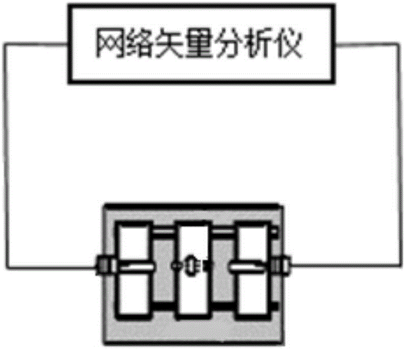
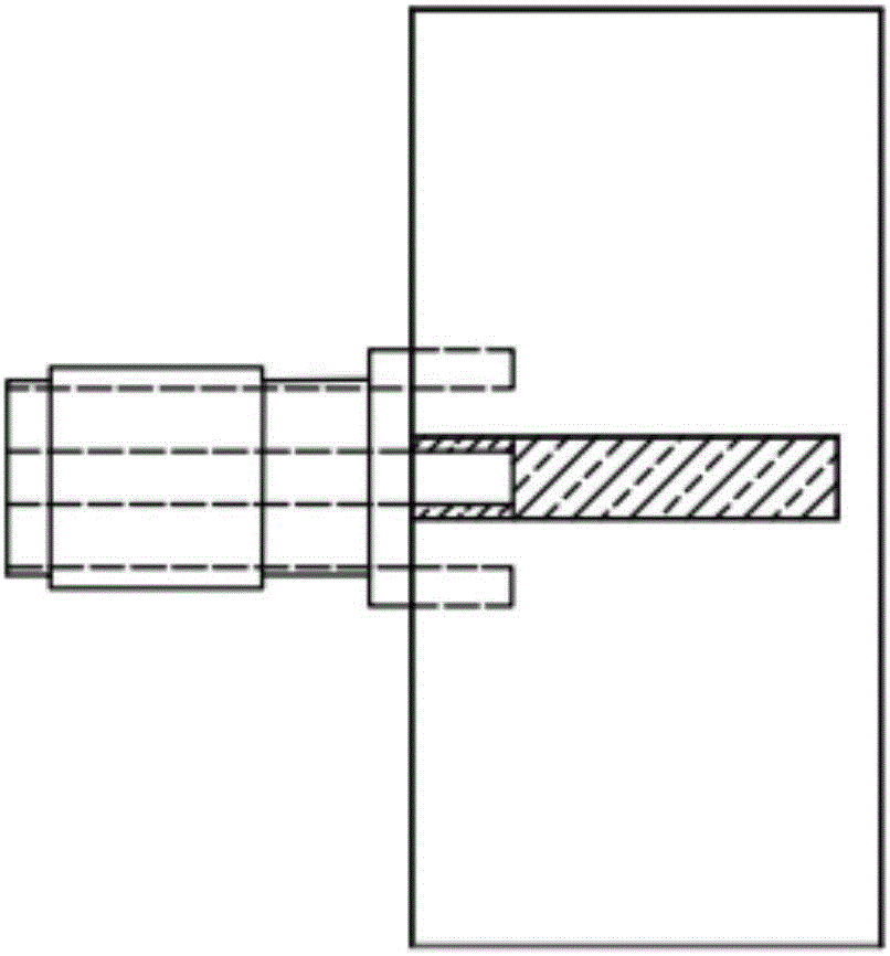
[0028] The measurement method of the present invention uses two circuits, one is a microstrip line circuit with a terminal loading resistance, and the other is a microstrip line circuit with a terminal short circuit. Microstrip line circuit with terminal loading resistance: chip resistors are connected to the end of the microstrip line, and the resistance value of the chip resistors greater than 50Ω is as close as possible to 50Ω in parallel, and the chip resistors are placed at equal intervals at the end of the microstrip line ; For chip resistors less than 50Ω, do not do connection processing, directly place a resistor in the middle of the end of the microstrip line. Microstrip line circuit with terminal short-circuit: the microstrip line should be equal in length and width to the microstrip line of the terminal loading resistor, and the end of the microstrip line is connected to a small microstrip line that is consistent with the total length and width of the terminal loadin...


PUM

PropertyMeasurementUnit
Characteristic impedanceaaaaaaaaaa

Abstract

The invention discloses a chip resistor impedance and standing-wave ratio frequency characteristic measuring device and method. The measuring device comprises a microstrip line circuit, the terminal end of which is loaded with chip resistors, a microstrip line circuit, the terminal end of which is short-circuited and a network vector analyzer. The input impedance of the microstrip line circuit, the terminal end of which is loaded with the chip resistors and the input impedance of the microstrip line circuit, the terminal end of which is short-circuited are measured through the network vector analyzer; furthermore, the impedance ZL of the chip resistors is calculated; and standing-wave ratio of the chip resistors is calculated according to the ZL. The microstrip line circuit, the terminal end of which is loaded with the chip resistors and the microstrip line circuit, the terminal end of which is short-circuited are combined to calculate the impedance and standing-wave ratio frequency characteristic and the standing-wave ratio of the chip resistors, so that a part of influence of electromagnetic wave reflection introduced by a measuring circuit can be counteracted, and the measuring result is more reliable.

Description

technical field [0001] The invention relates to the field of radio frequency microwave technology, in particular to a device and method for measuring the impedance and standing wave ratio frequency characteristics of a chip resistor in the radio frequency field. Background technique [0002] With the application and continuous development and improvement of microelectronic circuits and surface mount technology (SMT), the resistor industry as a whole is showing a trend towards chip and miniaturization. To miniaturize electronic equipment, the first thing to consider is the miniaturization of electronic components. Chip type and miniaturization have become the main development direction of resistance components in recent years. [0003] In order to reduce the cost and improve the precision of resistance value, laser trimming is generally used for chip resistors to make the chip resistors reach the expected resistance value on DC. [0004] The resistance value given on the ch...

Claims


Application Information

Patent Timeline
IPC IPC(8): G01R27/02
CPCG01R27/02
Inventor 曾柳杏林福民张逸松
Owner GUANGDONG UNIV OF TECH
Learn More