
Automatic target-scoring system and method for archery

An automatic, mirror-reflecting technology, used in target indicating systems, targets, javelin targets, etc., can solve the problems of cable 3 fatigue, unstable work, affecting accuracy, etc., to improve safety and reliability, and improve effectiveness and reliability. the effect of simplifying system design

Active Publication Date: 2016-11-16
SUOOTER TECH BEIJING LTD
View PDF5 Cites 2 Cited by
  • Summary
  • Abstract
  • Description
  • Claims
  • Application Information

AI Technical Summary

Problems solved by technology

like figure 1 As shown, the existing scanning archery automatic target reporting system mainly uses a fixed transmitter circuit (i.e. fixed emission light bands I and II) but a mobile receiver circuit (i.e. moves the active X-axis scanning head 1 and the active Y-axis respectively). Axis scan head 2) scans the entire archery target surface, because the receiver circuit needs to configure power supply (i.e. figure 1 The power supply I connected to the active X-axis scanning head 1 through the cable 3 shown in , and the power supply II) and signals connected to the active Y-axis scanning head 2 through the cable 3, so when the active X-axis scanning head 1 and the active Y-axis scanning head 2 move at their respective archery target frames, they need to drag the cable 3 to move quickly. This kind of system structure can easily lead to fatigue of the cable 3 after working for a long time. Moreover, the scanning head The circuit will also lead to unstable work during frequent scanning movements and start-stop vibrations, thereby affecting the effectiveness and reliability of the arrow impact point position acquisition, and at the same time affecting the safety and reliability of the archery automatic target reporting system, reducing the system The service life increases the system maintenance overhaul cycle and cost
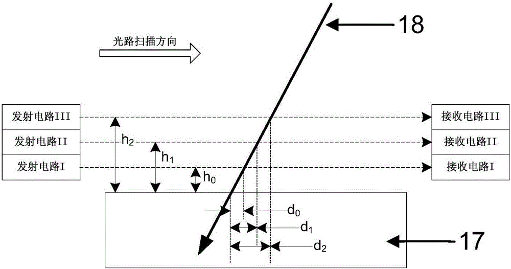
[0003] In addition, due to the fact that in the actual acquisition application, it is not possible to guarantee the vertical incidence every time when the arrow body hits the archery target. (that is, the receiver circuit configured on the active X-axis scanning head 1 and the active Y-axis scanning head 2) and the archery target surface, there is a certain height, so the position of the arrow landing point collected by the system is different from the actual arrow landing point. There is a certain error in the position of the point, which affects the accuracy of the acquisition of the arrow's point position, and at the same time affects the reliability of the archery automatic target reporting system

Method used


Image

  • Automatic target-scoring system and method for archery
  • Automatic target-scoring system and method for archery
  • Automatic target-scoring system and method for archery

Examples


Embodiment Construction

[0024] Below with the accompanying drawings ( Figure 2-Figure 3 ) to illustrate the present invention.

[0025] The invention relates to an automatic target reporting system for archery, which includes a horizontal optical path transmitting circuit, a horizontal optical path receiving circuit, a vertical optical path transmitting circuit, a vertical optical path receiving circuit and two scanning optical paths, and the horizontal optical path transmitting circuit and the horizontal optical path receiving circuit form a rectangle. The vertical side is fixedly arranged at both ends of the vertical side, the vertical optical path transmitting circuit and the vertical optical path receiving circuit are arranged on a horizontal side of the rectangle and are respectively fixedly arranged at both ends of the horizontal side, and the first scanning optical path is located in the rectangular between the upper horizontal side and the lower horizontal side and formed by reflection of th...


PUM


Abstract

The invention relates to an automatic target-scoring system and method for archery. The automatic target-scoring system for archery comprises a horizontal light path emitting circuit, a horizontal light path receiving circuit, a vertical light path emitting circuit and a vertical light path receiving circuit. Two scanning light paths with passive scanning heads and with light rays crossed are configured between the pair of emitting circuits and the pair of receiving circuits. The automatic target-scoring system for archery is simple in structure, the effectiveness and reliability of arrow landing position collection are high, the collection effect is good, the collection precision is high, and the system is high in safety and reliability.

Description

technical field [0001] The invention relates to the technical field of archery electronic equipment and systems, in particular to an archery automatic target reporting system and an automatic target reporting method based on a single set of passive optical path scanning of optical path reflection. Background technique [0002] At present, the archery target of archery class (such as sports archery competition) generally adopts the artificial target reporting mode of grass target. Now the archery target of archery class (such as sports archery competition) begins to adopt the scanning type archery automatic target reporting mode of rectangular archery target structure to obtain archery result data. The scanning archery automatic target reporting method usually uses the light emitted by the emission point of the emission light strip composed of the transmitter array to form a vertical cross light curtain and the movable receiver corresponding to the transmitter receives the li...

Claims


Application Information

Patent Timeline
IPC IPC(8): F41J3/00F41J5/02
CPCF41J3/0004F41J5/02
Inventor 孙波
Owner SUOOTER TECH BEIJING LTD
Learn More