
Under-table computer subrack mounting structure supporting sitting posture operation

A desktop computer and installation structure technology, applied in the direction of the computer workstation table or table, computing, instruments, etc., can solve the problems of poor operator comfort, difficult to read the panel, insufficient lighting, etc., to reduce the complexity and cost of the device, Improve debugging and maintainability, and avoid the effect of installing a follower device

Active Publication Date: 2021-02-12
TIANJIN QISUO PRECISION ELECTROMECHANICAL TECH
View PDF6 Cites 0 Cited by
  • Summary
  • Abstract
  • Description
  • Claims
  • Application Information

AI Technical Summary

Problems solved by technology

[0004] Due to the small space under the platform of the plug-in box, insufficient light, and the low position of the panel, it is difficult to operate, and it is not easy to read the identification information of the panel and the board inside the chassis
[0005] To sum up, the existing installation structure has disadvantages such as complicated operation, poor operator comfort, and long operation time.

Method used


Image

  • Under-table computer subrack mounting structure supporting sitting posture operation
  • Under-table computer subrack mounting structure supporting sitting posture operation
  • Under-table computer subrack mounting structure supporting sitting posture operation

Examples


Embodiment Construction

[0028] The present invention will be described in further detail below in conjunction with the drawings and specific examples. The following examples are only descriptive, not restrictive, and cannot limit the protection scope of the present invention.

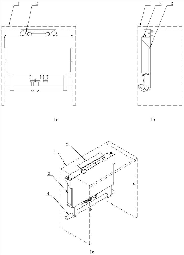
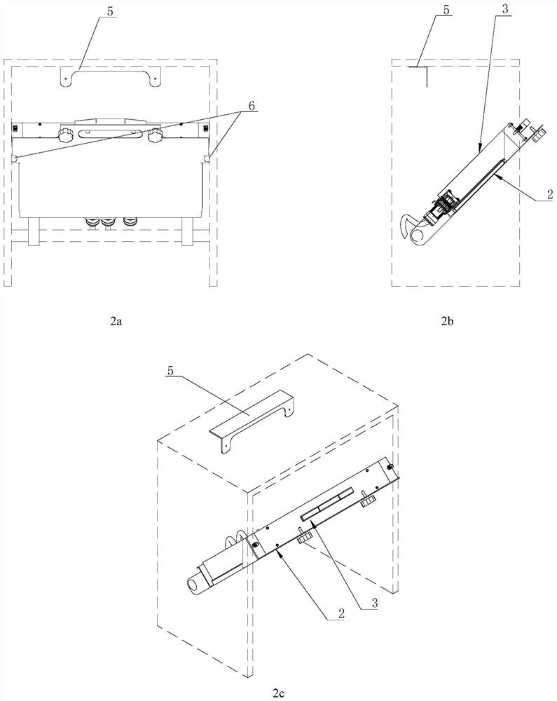
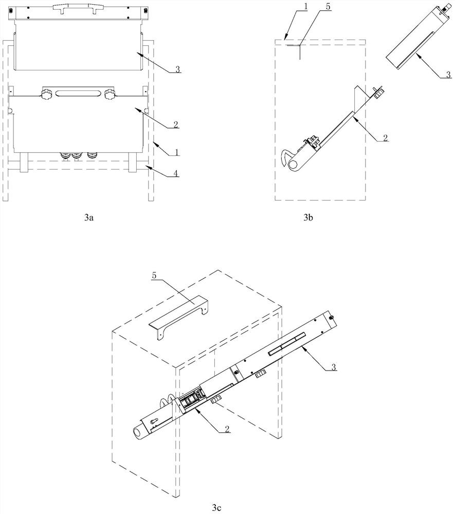
[0029] A plug-in box installation structure for a desktop computer operated in a sitting posture, see Figure 1-7 , Its invention point: comprise desk 1, bracket 2 and plug-in box 3, plug-in box is made of casing and the panel 3.1 that connects casing front and back end and backboard 3.2. Described carriage is arranged on the desktop below of desk, and the rear end of carriage forms hinged connection with the cross link 4 that is connected to the both sides of desk, and cross joint can adopt the cross link structure shown in accompanying drawing. The bracket is provided with a plug-in box installation platform 2.1, and the installation platform can adopt a right-angle surface composed of a plane and a vertical surface. The mo...


PUM


Abstract

The invention relates to a desk computer subrack mounting structure supporting sitting posture operation, which comprises a desk, a bracket and a subrack, and is characterized in that the rear end part of a towing bracket is hinged with transverse connecting pieces connected to two side edges of the desk; a plug-in box mounting table is arranged on the bracket, a collision connector fixed end is fixed at the rear side end of the plug-in box mounting table, a collision connector movable end is fixed at the plug-in box backboard end, and the plug-in box and the collision connector movable end are in plug-in fit; linear guide matching structures are arranged on the two sides of the plug-in box and the plug-in box mounting table; plug-in box limiting parts are arranged on two sides, close to the front end, of the plug-in box mounting table, and limiting baffles in contact with the plug-in box limiting parts are fixed on two sides of the panel at the front end of the plug-in box and are connected with fastening screws; limiting stoppers are fixedly mounted at the upper parts of the front ends of the two side edges of the table top; when the towing bracket rotates to a vertical positionaround the hinged connection point, the front end part of the subrack mounting table is in contact with the limiting frame and is connected with the limiting frame through a screw or a lock catch; andwhen the bracket rotates to the front inclined position around the hinged connection point, the towing bracket is in contact with the limiting stop piece. According to the invention, the installationand maintenance convenience is improved.

Description

technical field [0001] The invention belongs to the application fields of computer engineering and electronic engineering, and in particular relates to a box installation structure for a desktop computer supporting sitting posture operation. Background technique [0002] In the field of computer engineering and electronic engineering applications, reinforced computer sub-boxes and industrial computer sub-boxes (hereinafter referred to as sub-boxes) are installed at the lower rear of the desktop or the lower rear of the display console, and the position in front of the operator's knee is such an application scenario. The usual connection installation form. The user needs to perform maintenance and other operations on the subrack. The plug box is generally fixed under the table top by screws or slide rails. [0003] When operating the sub-box, it is necessary to pull the sub-box forward as a whole through the guide rail, or remove the sub-box, and operate the sub-box separat...

Claims


Application Information

Patent Timeline
IPC IPC(8): G06F1/18A47B21/00
CPCG06F1/181A47B21/00
Inventor 赵川陈立斌张智杰李刚周嘉湛青坡赵瑞营
Owner TIANJIN QISUO PRECISION ELECTROMECHANICAL TECH
Learn More