A centrifugal pump mechanical seal flushing device
A technology for mechanical seals and flushing devices, which is applied to mechanical equipment, components of pumping devices for elastic fluids, pumps, etc. The effect of preventing the deposition of particulate impurities and ensuring normal and stable operation
- Summary
- Abstract
- Description
- Claims
- Application Information
AI Technical Summary
Problems solved by technology
Method used
Image

Examples
Embodiment 1
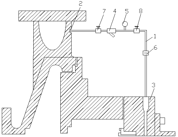
[0042] see figure 1 , a centrifugal pump mechanical seal flushing device, comprising a flushing pipe 1 connected to the centrifugal pump, the liquid inlet end of the flushing pipe 1 is connected to the outlet port 2 of the centrifugal pump, the liquid outlet end of the flushing pipe 1 is connected to the mechanical seal of the centrifugal pump 3 connection, the flushing pipe 1 is connected with a tubular filter 4, a pressure gauge 5 and a throttling orifice 6, the tubular filter 4 is close to the outlet end 2 of the centrifugal pump, and the throttling orifice 6 is close to The mechanical seal 3 of the centrifugal pump, the flushing pipe 1 is provided with a first shut-off valve 7 and a second shut-off valve 8, the first shut-off valve 7 is located between the outlet port 2 of the centrifugal pump and the tubular filter 4, The second stop valve 8 is located between the pressure gauge 5 and the throttle orifice 6 .
[0043] This embodiment is the most basic implementation mode...
Embodiment 2
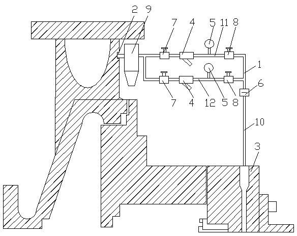
[0045] see figure 2 , a centrifugal pump mechanical seal flushing device, comprising a flushing pipe 1 connected to the centrifugal pump, the liquid inlet end of the flushing pipe 1 is connected to the outlet port 2 of the centrifugal pump, the liquid outlet end of the flushing pipe 1 is connected to the mechanical seal of the centrifugal pump 3 connection, the flushing pipe 1 is connected with a tubular filter 4, a pressure gauge 5 and a throttling orifice 6, the tubular filter 4 is close to the outlet end 2 of the centrifugal pump, and the throttling orifice 6 is close to The mechanical seal 3 of the centrifugal pump, the flushing pipe 1 is provided with a first shut-off valve 7 and a second shut-off valve 8, the first shut-off valve 7 is located between the outlet port 2 of the centrifugal pump and the tubular filter 4, The second stop valve 8 is located between the pressure gauge 5 and the throttle orifice 6 .
[0046] A suspension separator 9 is also included, one end o...
Embodiment 3
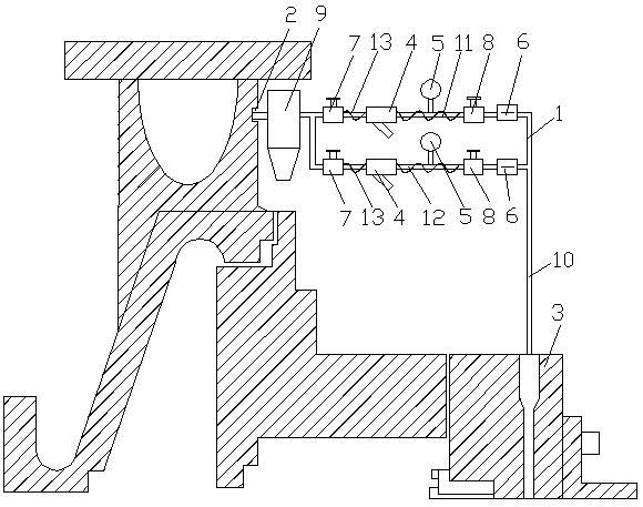
[0050] see image 3 , a centrifugal pump mechanical seal flushing device, comprising a flushing pipe 1 connected to the centrifugal pump, the liquid inlet end of the flushing pipe 1 is connected to the outlet port 2 of the centrifugal pump, the liquid outlet end of the flushing pipe 1 is connected to the mechanical seal of the centrifugal pump 3 connection, the flushing pipe 1 is connected with a tubular filter 4, a pressure gauge 5 and a throttling orifice 6, the tubular filter 4 is close to the outlet end 2 of the centrifugal pump, and the throttling orifice 6 is close to The mechanical seal 3 of the centrifugal pump, the flushing pipe 1 is provided with a first shut-off valve 7 and a second shut-off valve 8, the first shut-off valve 7 is located between the outlet port 2 of the centrifugal pump and the tubular filter 4, The second stop valve 8 is located between the pressure gauge 5 and the throttle orifice 6 .
[0051] A suspension separator 9 is also included, one end of...
PUM
 Abstract
Description
Claims
Application Information
 - R&D
- Intellectual Property
- Life Sciences
- Materials
- Tech Scout
- Unparalleled Data Quality
- Higher Quality Content
- 60% Fewer Hallucinations
Browse by: Latest US Patents, China's latest patents, Technical Efficacy Thesaurus, Application Domain, Technology Topic, Popular Technical Reports.
© 2025 PatSnap. All rights reserved.Legal|Privacy policy|Modern Slavery Act Transparency Statement|Sitemap|About US| Contact US: help@patsnap.com