
Self-adaptive controlled safe seat in back row of automobile and control method

An adaptive control, safety seat technology, applied in vehicle seats, vehicle parts, special positions of vehicles, etc., can solve problems such as affecting the comfort of passengers, the seat can not be well protected, and achieve a fast action mode. , has the effect of controllability and quick response

Inactive Publication Date: 2016-11-16
JIANGSU UNIV
View PDF7 Cites 10 Cited by
  • Summary
  • Abstract
  • Description
  • Claims
  • Application Information

AI Technical Summary

Problems solved by technology

The seat is a passive reaction mechanism, which drives the seat to turn over a certain angle through the inertial force of the occupant and the seat itself, but the inertial force is related to the weight of the passenger, and those who are light or heavy may affect the turning angle, causing the seat to It cannot play a good protective role. At the same time, due to the action of the spring, the seat cushion will be turned over at a certain angle under various braking conditions, and the frequent shaking of the seat will affect the comfort of the passengers when riding.

Method used


Image

  • Self-adaptive controlled safe seat in back row of automobile and control method
  • Self-adaptive controlled safe seat in back row of automobile and control method
  • Self-adaptive controlled safe seat in back row of automobile and control method

Examples


Embodiment Construction

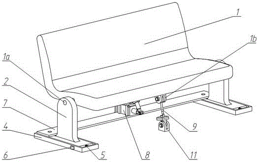
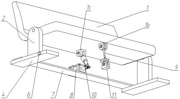
[0023] see figure 1 , figure 2 , the left and right sides of the seat body 1 are respectively connected to the top of the seat frame 2 through a rotating shaft 1a, the central axis of the rotating shaft 1a is arranged along the left and right directions, and the two seat frames 2 on the left and right sides are all vertically arranged, and the seat body 1 can rotate back and forth on the two seat frames 2 around the axis of rotation 1a.

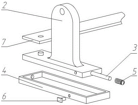
[0024] see figure 2 , image 3 , the seat body 1 bears the weight of the occupant, and the seat frame 2 supports the weight of the seat body 1 and the human body and participates in the movement of the seat body 1 during semi-active protection control. The seat frame 2 bottom is installed in the chute 4, and there is a section of space between the seat frame 2 bottom and the chute 4 front, for installing the guide rod 3 and the spring 5. The guide rod 3 and the spring 5 are connected between the front end of the lower part of the seat f...


PUM


Abstract

The invention discloses a self-adaptive controlled safe seat in a back row of an automobile and a control method. A seat body can rotate forwards and backwards around a rotating shaft; the lower part of each seat frame is arranged in a corresponding sliding groove and can move forwards in the corresponding sliding groove; an electromagnetic valve is mounted at the side part of each of the sliding grooves; an iron core of each of the electromagnetic valves can extend into a hole in the side surface of the corresponding seat frame to prevent the seat frame from moving forwards; a fixing plate which is not in contact with the sliding grooves is fixedly connected between the rear part of the left side seat frame and the rear part of the right side seat frame; the middle part of the fixing plate is fixedly connected with explosion cylinders in front-back arrangement; the front ends of the explosion cylinders are hinged to the lower end of a pull rod through a cylinder push rod; the upper end of the pull rod is hinged to the bottom surface of the rear part of the seat body, and the pull rod is a telescopic rod with expansion and contraction quantity; the front part of the bottom surface of the seat is hinged to the upper end of a top rod through a front part pin seat; and the lower end of the top rod is hinged to a bottom plate pin seat through the bottom plate pin seat. When the safe seat is under an initial condition, the top rod tilts from a rear upper part to a front lower part; and when being subjected to tensile force exceeding a predetermined intensity, the top rod can be broken, and a protecting condition can be automatically shifted according to the changes of the acceleration of the automobile.

Description

technical field [0001] The invention belongs to the field of motor vehicle seat safety, in particular to the rear seats installed in the vehicle compartment, which can protect the safety of the passengers in the rear row when the motor vehicle is collided. Background technique [0002] In recent years, studies on automobile collision safety have found that during emergency braking or collision, increasing the angle between the car seat cushion and the vehicle floor can protect the occupant's abdomen and lower limbs and prevent submersion, avoiding The occupant suffered secondary injuries. For car safety seats, most of the current existing solutions use motors as actuators. The actuators can change the structure of the seat and protect passengers after receiving the acceleration signal during a collision. However, these safety seats Most of the protection measures are aimed at the safety of the main driver's seat in the front row, and there are relatively few designs for the...

Claims


Application Information

Patent Timeline
IPC IPC(8): B60N2/427B60N2/015
CPCB60N2/015B60N2/4214B60N2/42736B60N2/4279
Inventor 江洪王子豪苏俊杰马也
Owner JIANGSU UNIV
Learn More