
Mounting bracket for mounting engine to left suspension

A technology of mounting bracket and left suspension, which is applied in the direction of power plant, transportation and packaging, jet propulsion device, etc., and can solve the requirements that affect the strength of the engine mounting bracket, the layout structure requirements, the structure design of the engine mounting bracket cannot be satisfied, and the whole vehicle Performance impact and other issues, to achieve the effect of improving mechanical properties and pass rate, increasing service life, and compact use strength requirements

Inactive Publication Date: 2016-11-16
宁国市中泰汽车零部件有限公司
View PDF6 Cites 2 Cited by
  • Summary
  • Abstract
  • Description
  • Claims
  • Application Information

AI Technical Summary

Problems solved by technology

[0002] The left mount engine mounting bracket is an important part installed at the left end of the engine. It has the function of installing the engine assembly on the left mount. With the continuous increase of new technologies, the current vehicle layout has been developing in a compact direction. The space inside is becoming more and more tight; in order to meet the layout requirements, the structural design of the engine mounting bracket can no longer meet the development of existing vehicle technology
For example, when the steering system is arranged as a whole vehicle, the layout space of the lower transmission shaft of the steering system will conflict with the engine mounting bracket. To solve this problem, the existing technology avoids interference by changing the layout position of the engine mounting bracket, which will affect the engine. The use strength requirements of the mounting bracket and the layout structure requirements will affect the performance of the vehicle

Method used


Image

  • Mounting bracket for mounting engine to left suspension

Examples


Embodiment Construction

[0018] The present invention will be further described in detail below in conjunction with the drawings and specific embodiments.

[0019] The present invention adopts the following technical solutions:

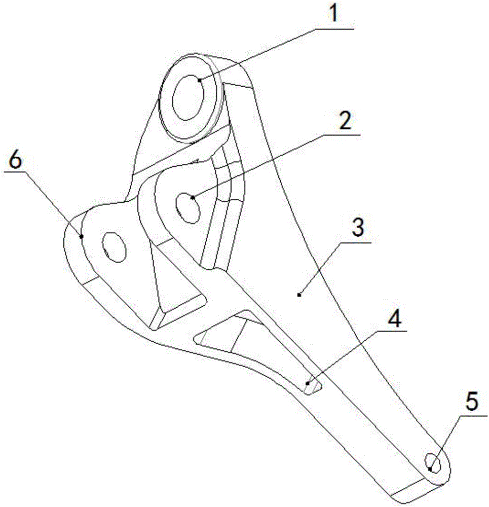
[0020] A left-mounted engine mounting bracket, comprising: a connecting rod 3, the top of the connecting rod 3 is provided with a left-mounted anti-rotation hole 1 for fixing anti-rotation, and anti-rotation bolts can be installed in the holes to prevent tightening of nuts When the engine suspension rotates under the action of the tightening force, the rear part of the connecting rod 3 is provided with a left suspension connecting hole 5 to realize the assembly connection of the left suspension engine mounting bracket and the vehicle body; the middle part of the connecting rod 3 is provided with Cavity 4, two arc-shaped lugs 6 are arranged between the cavity 4 and the left suspension anti-rotation hole 1, and a left suspension mounting hole 2 is provided on each of the two lugs 6,...


PUM

PropertyMeasurementUnit
thicknessaaaaaaaaaa
tensile strengthaaaaaaaaaa

Abstract

The invention relates to a mounting bracket for mounting an engine to a left suspension. The mounting bracket comprises a connecting rod, a left suspension rotation preventing hole, a left suspension connecting hole, an empty cavity, a lug and a left suspension mounting hole. The mounting bracket is manufactured from the following selected manufacturing materials of 10-15% of silicon, 0.2-0.5% of magnesium, copper which is 0.5% or below, 0.15-0.4% of manganese, 0.3-0.8% of iron, 0.1-0.5% of zinc, 0.03-0.08% of titanium, 0.03-0.05% of strontium, 0.1-0.3% of zirconium, 0.1-0.3% of chromium, 0.15-0.2% of rare-earth element, and the balance aluminum and inevitable impurities. The selected manufacturing materials of the mounting bracket disclosed by the invention meet the requirements of casting and processing for properties of alloy, so that the mechanical properties and the qualification rate of the mounting bracket for mounting the engine to the left suspension can be improved. The using strength requirements for an engine mounting bracket and the requirement of being compact in an arranging structure are met in the structure of the mounting bracket disclosed by the invention, and the integral properties of the vehicle are improved.

Description

Technical field [0001] The invention relates to the technical field of automobile engines, in particular to a left-mounted engine mounting bracket. Background technique [0002] The left-mounted engine mounting bracket is an important part installed at the left end of the engine. It has the function of installing the engine assembly on the left mounting. With the continuous increase of new technologies, the current vehicle layout has been developing in a compact direction. The internal space is becoming more and more tight; in order to meet the layout requirements, the structural design of the engine mounting bracket can no longer meet the development of existing vehicle technology. For example, when the steering system is deployed in the whole vehicle, the layout space of the lower drive shaft of the steering system will conflict with the engine mounting bracket. To solve this problem, the prior art avoids interference by changing the layout position of the engine mounting brack...

Claims


Application Information

Patent Timeline
Patent Type & Authority Applications(China)
IPC IPC(8): B60K5/12C22C21/02
CPCB60K5/12C22C21/02
Inventor 江登惠
Owner 宁国市中泰汽车零部件有限公司
Learn More