
A manual looper

A technology of looper and probe, which is applied in the field of probe card production equipment, can solve the problems affecting the quality level of probe card, the length of looper, and the large difference in angle, so as to save training and education costs, improve production cycle and efficiency , the effect of simple operation

Active Publication Date: 2017-11-28
DALIAN HUOLAN ELECTRONICS TECH CO LTD
View PDF5 Cites 0 Cited by
  • Summary
  • Abstract
  • Description
  • Claims
  • Application Information

AI Technical Summary

Problems solved by technology

At present, the looper is mainly completed manually with the help of simple molds. In this production mode, there are large differences in the length and angle of the looper, which cannot be controlled within the reasonable deviation requirements, thus affecting the quality level of the entire probe card.

Method used


Image

  • A manual looper
  • A manual looper

Examples


Embodiment Construction

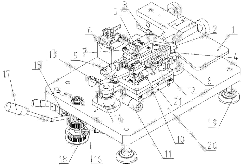
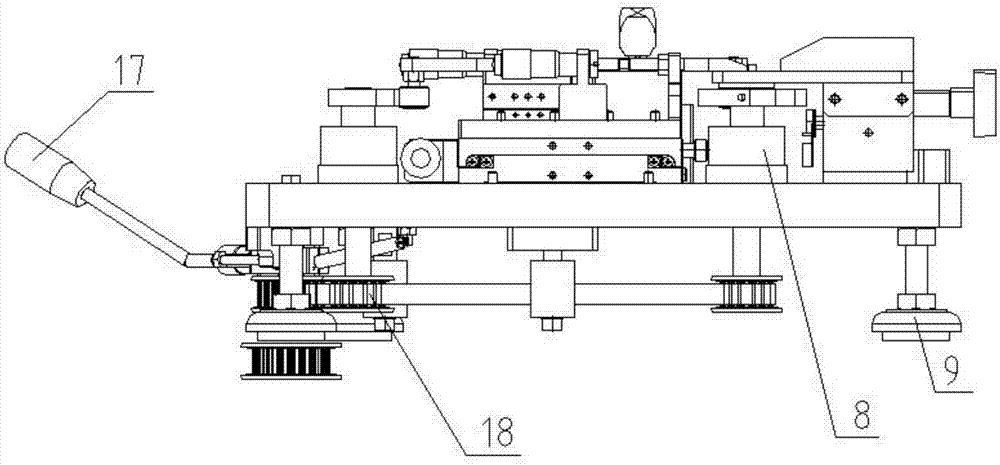
[0019] Attached below Figure 1-2 The present invention is described further:

[0020] A manual needle looper, comprising a working surface 20, which is provided with a probe clamping mechanism connected to a transmission device, an X-direction positioning mechanism and a looper mechanism, an end of the X-direction positioning mechanism and a probe clamping mechanism The end is located on the looper mechanism and said transmission is connected to the drive handle 17 .

[0021] The probe clamping mechanism is located on the Y-direction adjustment slide 12, and the Y-direction adjustment slide 12 is located on the fixed slide 21 and is connected to the Y-direction position adjustment screw 11, and the fixed slide 21 is fixed on the working surface 20 .

[0022] The probe clamping mechanism includes a Y upward clamping knife 3 located on the Y-direction clamping movement slide table 7, and a Y downward clamping knife 4 is provided on the opposite side of the Y upward clamping k...


PUM


Abstract

The invention discloses a manual probe bending machine, and belongs to the technical field of probe card manufacturing equipment. The manual probe bending machine comprises a working table-top; a probe clamping mechanism connected with a transmission device, an X-direction locating mechanism and a probe bending mechanism are arranged on the working table-top; the end part of the X-direction locating mechanism and the end part of the probe clamping mechanism are located on the probe bending mechanism; and the transmission device is connected with a driving handle. Through technological innovation, a probe after probe bending can meet the design requirements, the quality of the probe can reach the standard, the operation is simple, and the production cycle and the efficiency are improved; the operation by multiple workers in one post can be realized better, and the operation of the manual probe bending machine can be learned and mastered easily, so that the training and education cost of an enterprise can be saved; the deviations of the length and the angle of the probe after the probe bending are reduced to the greatest extent, the precision of the probe for the manufacture of a probe card is improved, and the production requirements are met; and with the additional adoption of a Y-direction clamping auxiliary strengthening device, probe bending work on the probe with the diameter being greater than 350 micrometers can be realized.

Description

technical field [0001] The invention relates to a needle looper and belongs to the technical field of probe card manufacturing equipment. Background technique [0002] In the production process of semiconductors, probe cards are required to detect ICs. Since the detection position and spacing of ICs are very small and precise, this requires the probe cards to be very precise and have strict specifications during the production process. The production process of the probe card includes design, bending, needle setting, resin curing, welding, needle point grinding, needle position adjustment, testing and other main processes, and the bending process is the most important in the production of the probe card. very critical. At present, the looper is mainly completed manually with the help of simple molds. In this production mode, there are large differences in the length and angle of the looper, which cannot be controlled within the reasonable deviation requirements, thus affect...

Claims


Application Information

Patent Timeline
Patent Type & Authority Patents(China)
IPC IPC(8): B21F1/00
CPCB21F1/002
Inventor 张继李祥峰
Owner DALIAN HUOLAN ELECTRONICS TECH CO LTD
Learn More