
a soup maker

A soup machine and knife holder technology, applied in the field of soup cooking machines, can solve the problems that the knife holder cannot be disassembled, inconvenient to use, and difficult to clean the crushing tools, etc., and achieves the effects of comprehensive rotation function, wide application range and diversified functions.

Active Publication Date: 2019-01-04
NINGBO HUABAO PLASTICS & RUBBER MOLD
View PDF7 Cites 0 Cited by
  • Summary
  • Abstract
  • Description
  • Claims
  • Application Information

AI Technical Summary

Problems solved by technology

[0002] The soup cooking machine used on the market includes a cup cover, a cup body, a knife rest located in the cup body, a crushing knife arranged on the knife rest, a motor driving the knife rest to rotate, and a heating device located under the cup body. The motor shaft in the soup machine generally passes through the bottom of the cup body and is fixedly connected to the knife holder in the cup body, which brings certain defects: the knife holder cannot be disassembled, and the grinding tool is difficult to clean, which brings inconvenience to use

Method used


Image

  • a soup maker
  • a soup maker
  • a soup maker

Examples


Embodiment Construction

[0031] The present invention will be further described below in conjunction with the accompanying drawings and embodiments.

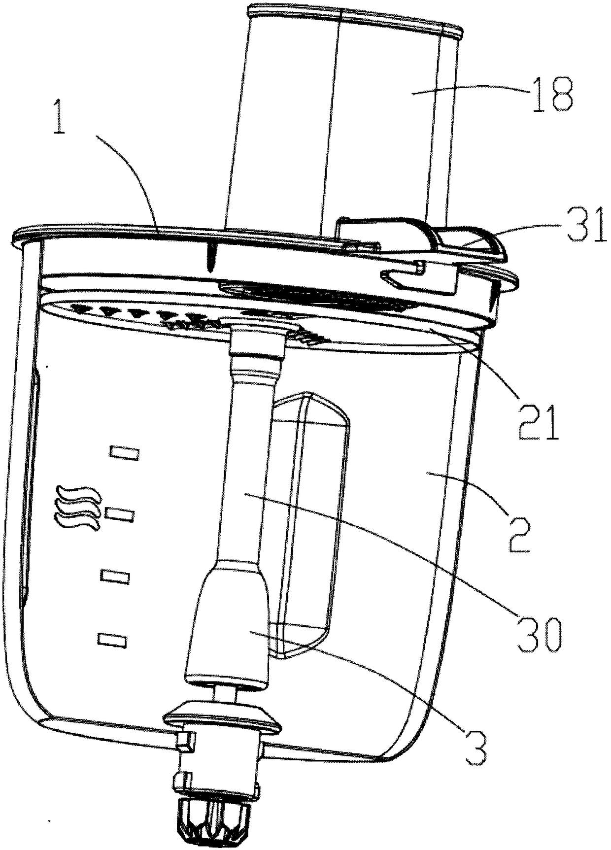
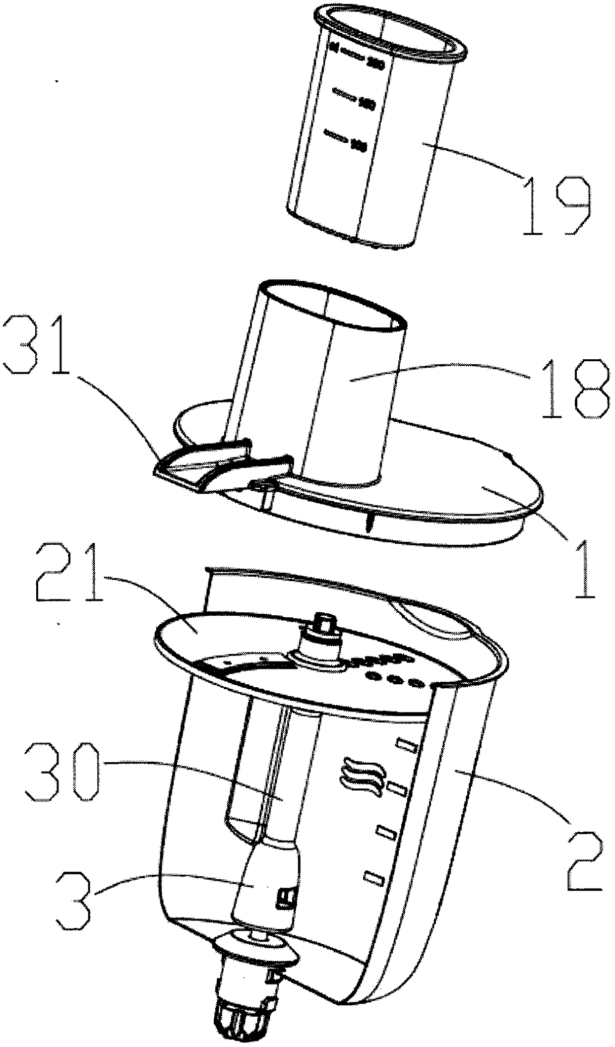
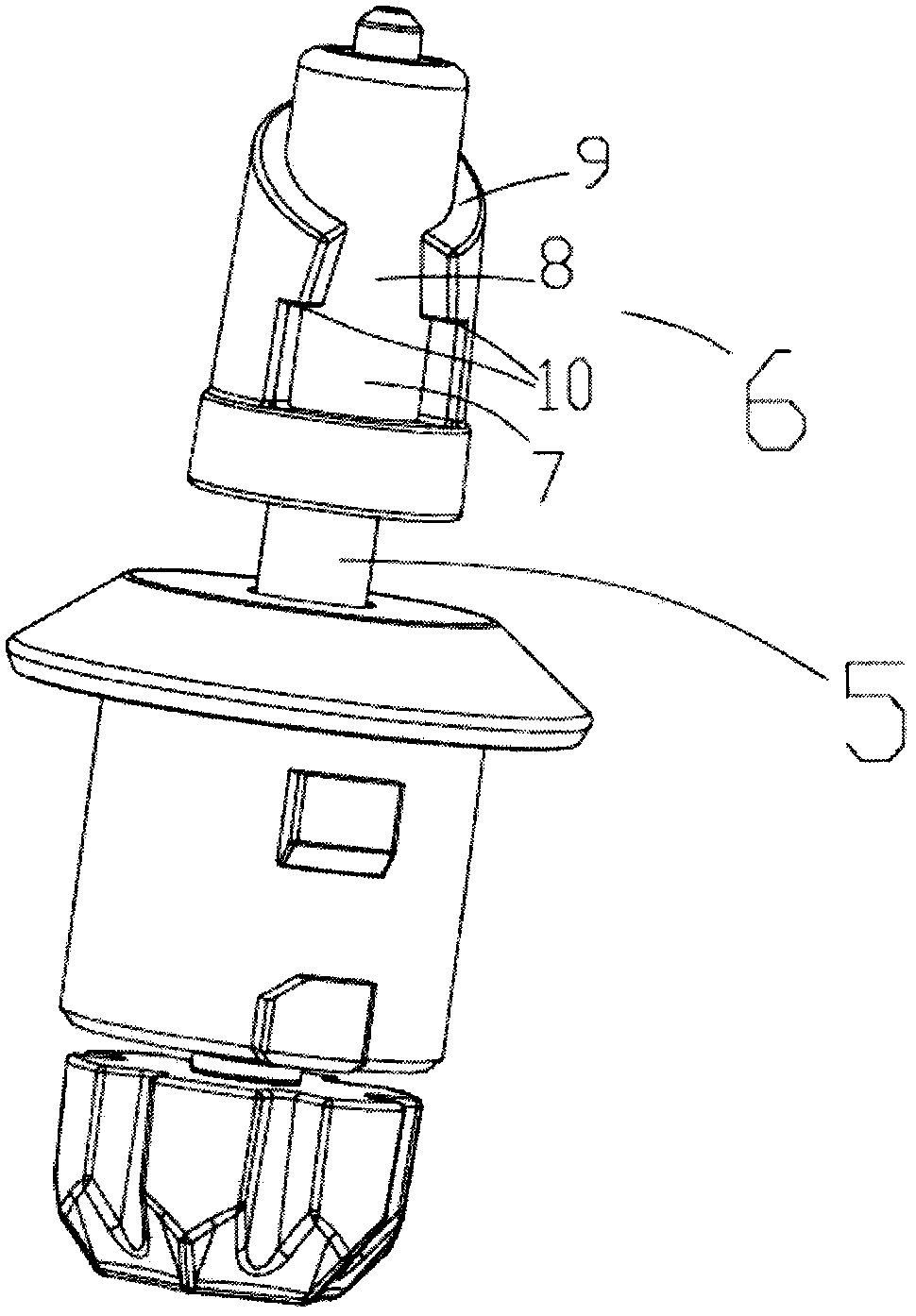
[0032] like figure 1 , 2 , 3, and 4, a kind of soup cooking machine provided by the present invention includes a cup cover 1, a cup body 2, a knife rest 3 arranged in the cup body and a crushing cutter arranged on the knife rest, and the knife rest is designed to There is a columnar structure with a mounting hole 4, the tool holder is sheathed and assembled on the main shaft 5, and a locking part 6 fixed to the mounting hole is provided on the main shaft.

[0033] The locking part 6 is continuously arranged as a locking groove 7 , a guiding groove 8 and a guiding inclined surface 9 along the axial direction of the main shaft, and an engaging part accommodated in the locking groove is provided in the mounting hole.

[0034] Wherein the locking part 6 is arranged at one end of the power output of the main shaft 5, the locking groove 7 is formed by the o...


PUM


Abstract

The invention discloses a soup cooker which comprises a cup lid, a cup body, a tool rest arranged inside the cup body and a smashing tool arranged on the tool rest. The tool rest is of a cylindrical structure with an installation hole. A main shaft is sleeved with the tool rest. The main shaft is provided with a locking portion fixed to the installation hole. Due to close fit of the installation hole and the main shaft, the tool and the main shaft are detachably connected, the tool is disassembled to clean the tool bit, and cleaning is convenient.

Description

technical field [0001] The invention relates to a soup cooking machine. Background technique [0002] The soup cooking machine used on the market includes a cup cover, a cup body, a knife rest located in the cup body, a crushing knife arranged on the knife rest, a motor driving the knife rest to rotate, and a heating device located under the cup body. The motor shaft in the soup maker generally passes through the bottom of the cup body and is fixedly connected to the knife holder in the cup body, which brings certain defects: the knife holder cannot be disassembled, and the cleaning of the crushing tool is difficult, which brings inconvenience in use. Contents of the invention [0003] In order to solve the above-mentioned deficiencies in the prior art, the object of the present invention is to provide a soup cooking machine with a detachable knife rest. [0004] In order to achieve the above object, a kind of soup cooking machine designed by the present invention include...

Claims


Application Information

Patent Timeline
Patent Type & Authority Patents(China)
IPC IPC(8): A47J27/00A47J43/044A47J43/07
CPCA47J27/004A47J43/044A47J43/0705A47J43/0711A47J2043/04454
Inventor 华明伟王建永袁海定陈鹏王军川马春花
Owner NINGBO HUABAO PLASTICS & RUBBER MOLD
Learn More