Method of Eliminating DC Offset in Cot Ripple Compensation Circuit

A technology of ripple compensation and DC offset, applied to electrical components, output power conversion devices, etc., can solve problems such as large output DC offset, and achieve the effect of output offset elimination

Inactive Publication Date: 2018-07-20
UNIV OF ELECTRONICS SCI & TECH OF CHINA
View PDF4 Cites 0 Cited by
  • Summary
  • Abstract
  • Description
  • Claims
  • Application Information

AI Technical Summary

Problems solved by technology

Generally, the COT technology based on ripple control has a design compromise between the noise margin and the amount of DC offset introduced on the output. High noise immunity requires the compensation ripple to have sufficient amplitude, which will bring greater Output DC offset, the defect of DC offset is very prominent in high-precision applications

Method used


Image

  • Method of Eliminating DC Offset in Cot Ripple Compensation Circuit
  • Method of Eliminating DC Offset in Cot Ripple Compensation Circuit
  • Method of Eliminating DC Offset in Cot Ripple Compensation Circuit

Examples


Embodiment Construction

[0033] The present invention will be further elaborated below in conjunction with the accompanying drawings and specific embodiments.

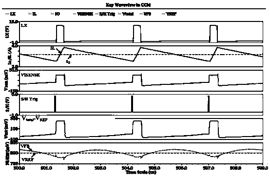
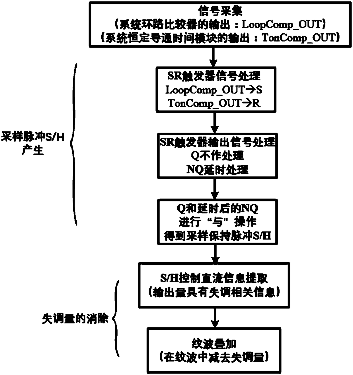
[0034] Such as figure 2 It is a flow chart of the DC offset elimination method in the COT ripple compensation circuit proposed by the present invention, including the sampling pulse S / H generation process and the offset elimination process.

[0035] The implementation of the DC offset elimination method in the COT ripple compensation circuit proposed by the present invention is shown in the figure image 3 As shown in the block diagram, the inductor current ripple information after half-period sampling is amplified by K times full differential through the pre-amplifier, and then sent to the DC flow extraction circuit for DC flow extraction. The core of the present invention lies in the generation of DC flow extraction pulses and the coordination The ripple summing circuit subtracts the extracted amount.

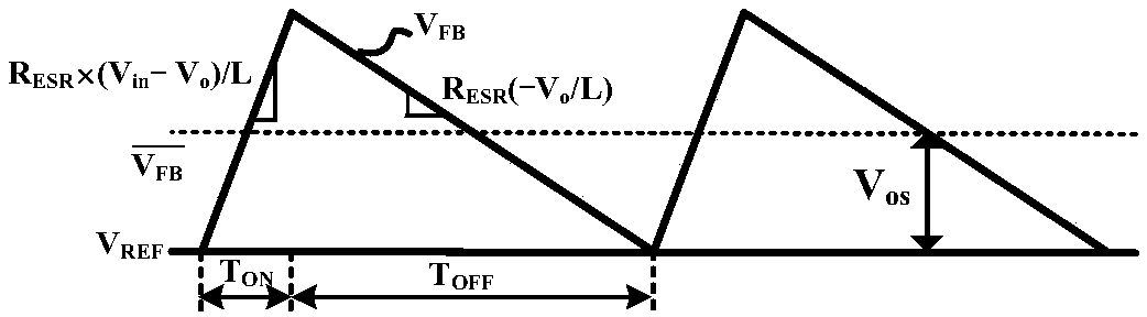
[0036] The ripple DC flow extractio...


PUM


Abstract

The invention relates to a method for eliminating DC offset in a COT ripple compensation circuit, belonging to the technical field of power supply management. Including the sampling pulse S / H generation process and the offset elimination process, during the sampling pulse S / H generation process, the output signal LoopCom_OUT of the loop comparator of the acquisition system is input to the set terminal S of the SR flip-flop, and the constant on-time module of the acquisition system The output signal TonComp_OUT of the SR flip-flop is input to the clearing terminal R of the SR flip-flop, and the signal output from the inverting output terminal NQ of the SR flip-flop is delayed and processed, and the signal output from the non-inverting output terminal Q is jointly input to the AND gate for AND operation to obtain sample and hold Pulse S / H; In the process of offset elimination, sample and hold pulse S / H is used to control the extraction of DC information, and the extracted DC information is used in the ripple superposition module to eliminate the offset of the output voltage. The invention implements the output offset elimination of the converter by adding a DC offset elimination method in the DC flow extraction circuit without adding an additional offset elimination circuit.

Description

technical field [0001] The invention belongs to the technical field of power management, and in particular relates to a method for eliminating the output DC offset of a step-down converter with a constant on-time (Constant On Time, COT) control framework. Background technique [0002] Compared with the voltage control mode and the peak current control mode, the COT control mode does not require an error amplifier in the traditional sense, which enables the COT control mode to provide faster transient response while maintaining accuracy; the COT control mode provides The frequency stabilization within the full input voltage range is of great significance to the anti-electromagnetic interference characteristics; at the same time, the improvement of the efficiency of the COT control mode under light load is in line with the development trend of electronic products at the current stage. The COT control architecture is favored among power management chips. [0003] While COT bri...

Claims


Application Information

Patent Timeline
Patent Type & Authority Patents(China)
IPC IPC(8): H02M1/14
CPCH02M1/143
Inventor 明鑫李天生徐俊王卓张波
Owner UNIV OF ELECTRONICS SCI & TECH OF CHINA
Why Eureka
Try Eureka