
Ultra-wide plane monopole antenna array, communication device and terminal device

A technology of monopole antennas and antenna arrays, applied in antenna arrays, antenna components, antennas, etc., can solve the problems of UWBMIMO antenna array complex structure, complex decoupling structure, and radiation performance changes, so as to expand bandwidth and reduce interaction Coupling, the effect of stabilizing radiation performance

Inactive Publication Date: 2016-11-09
SHENZHEN TINNO WIRELESS TECH
View PDF7 Cites 5 Cited by
  • Summary
  • Abstract
  • Description
  • Claims
  • Application Information

AI Technical Summary

Problems solved by technology

However, this implementation makes the structure of the UWB MIMO antenna array complex and increases in size, the radiation performance changes, and the decoupling structure is complicated.

Method used


Image

  • Ultra-wide plane monopole antenna array, communication device and terminal device
  • Ultra-wide plane monopole antenna array, communication device and terminal device
  • Ultra-wide plane monopole antenna array, communication device and terminal device

Examples


Embodiment 1

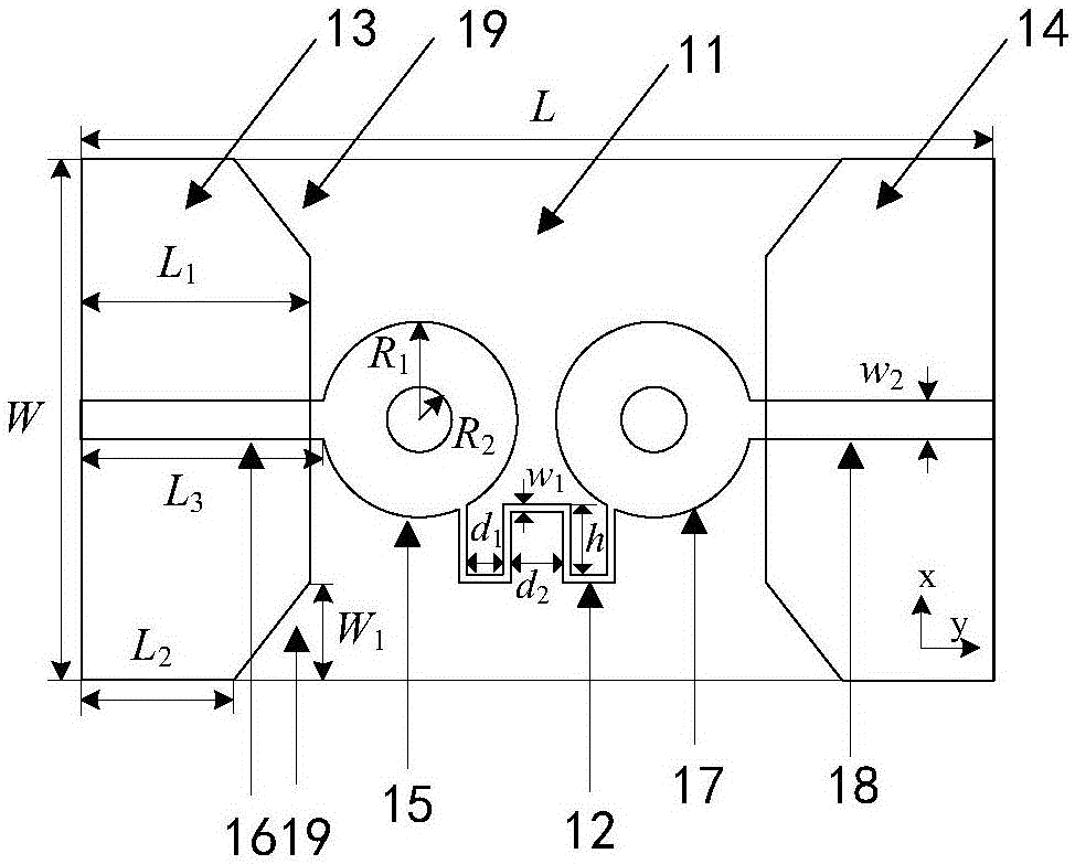
[0035] An embodiment of the present invention provides an ultra-wideband planar monopole antenna array, refer to figure 1 As shown, the antenna array includes:

[0036] The dielectric substrate 11 and the neutral line 12 are printed symmetrically along the first center line of the dielectric substrate 11. The first ground plate 13 and the second ground plate 14 on the lower surface of the dielectric substrate 11 are printed symmetrically along the first center line of the dielectric substrate 11. The radiation patch 15 and the microstrip feeder 16 of the first planar monopole antenna on the upper surface of the dielectric substrate 11 , and the radiation patch 17 and the microstrip feeder 18 of the second planar monopole antenna.

[0037] Optionally, the dielectric substrate 11 of the antenna array is FR4 material with a relative permittivity of 4.4 and a thickness of 1.6mm, its loss tangent is 0.02, and its dimensions are W=40mm and L=80mm.

[0038] from figure 1 It can be ...

Embodiment 2

[0054] An embodiment of the present invention provides a communication device, such as Figure 4 As shown, the communication device includes:

[0055] A wireless transceiver 41, and the antenna array 42 as described in the above embodiments, the wireless transceiver 41 is connected to the antenna array 42.

Embodiment 3

[0057] An embodiment of the present invention provides a terminal device, such as Figure 5 As shown, the terminal equipment includes:

[0058] The processor 51 , the memory 52 , and the above-mentioned communication device 53 are connected through the bus 54 .


PUM

PropertyMeasurementUnit
Thicknessaaaaaaaaaa
Sizeaaaaaaaaaa

Abstract

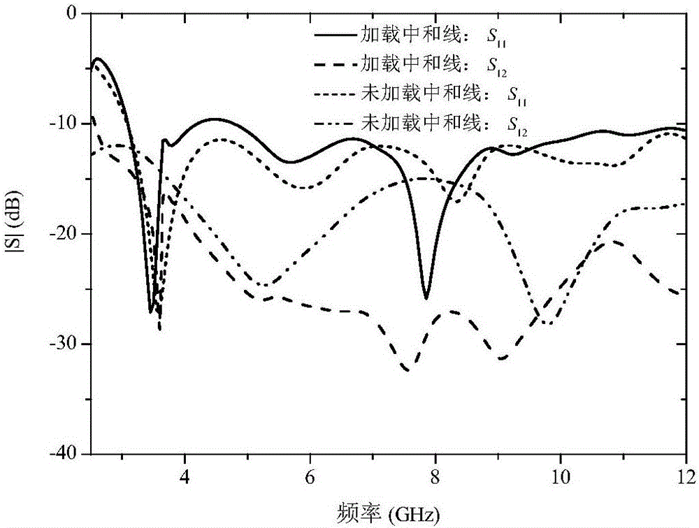
The embodiments of the invention provide an ultra-wide plane monopole antenna array, a communication device and a terminal device. The antenna array includes a medium substrate, a neutralizing wire, and a first earth plate and a second earth plate which are symmetrically printed on a lower surface of the medium substrate along a first central line of the medium substrate, and a radiation patch and a microstrip feeder of a first plane monopole antenna and a radiation patch and a microstrip feeder of a second plane monopole antenna which are symmetrically printed on an upper surface of the medium substrate along the first central line of the medium substrate; specified edges of the first earth plate and the second earth plate have symmetrical recessed parts, a specified edge being an edge approaching the first central line of the medium substrate, the symmetrical recessed parts being symmetrical around a second central line of the medium substrate, and the second central line being perpendicular to the first central line; two ends of the neutralizing wire are respectively connected to the radiation patch of the first plane monopole antenna and the radiation patch of the second plane monopole antenna. The loading of the neutralizing wire on the antenna array greatly intensifies isolation level among antenna array elements.

Description

【Technical field】 [0001] The invention relates to the technical field of communication, in particular to an ultra-wideband planar monopole antenna array, a communication device and a terminal device. 【Background technique】 [0002] Modern wireless communication systems require higher data transmission rates, greater channel capacity and wider communication frequency bands. Ultra Wideband (UWB) technology is widely used in various wireless devices due to its unique characteristics. The expanded bandwidth realizes high data rate transmission, and the inherent robustness of multipath propagation ensures high reliability. sex. [0003] With the increasing application of UWB technology in Multiple-Input Multiple-Output (MIMO) antenna systems, UWB MIMO antennas have attracted great attention in both academic and industrial fields. Ultra-wideband and high isolation are the primary goals of UWB MIMO antenna systems. In the prior art, different technologies are used to implement UW...

Claims


Application Information

Patent Timeline
IPC IPC(8): H01Q1/48H01Q1/38H01Q1/52H01Q21/00H01Q1/24
CPCH01Q1/24H01Q1/241H01Q1/38H01Q1/48H01Q1/523H01Q21/00
Inventor 于彦涛李萌易礼君刘晓亚
Owner SHENZHEN TINNO WIRELESS TECH
Learn More