
Polarization beam splitter

A technology of polarization beam splitter and coupling area, which is applied in the direction of instruments, light guides, optics, etc., can solve the problems of large bandwidth and high extinction ratio of polarization beam splitters, and achieve large working bandwidth, low loss and high application value Effect

Active Publication Date: 2016-11-09
PEKING UNIV
View PDF7 Cites 11 Cited by
  • Summary
  • Abstract
  • Description
  • Claims
  • Application Information

AI Technical Summary

Problems solved by technology

[0005] The present invention provides a polarization beam splitter to solve the problem that the polarization beam splitter in the existing solution cannot simultaneously satisfy a higher extinction ratio and a larger bandwidth

Method used


Image

  • Polarization beam splitter
  • Polarization beam splitter
  • Polarization beam splitter

Examples


Embodiment Construction

[0027] In order to make the purpose, technical solutions and advantages of the embodiments of the present invention clearer, the technical solutions in the embodiments of the present invention will be clearly described below in conjunction with the accompanying drawings in the embodiments of the present invention. Obviously, the described embodiments are the Some, but not all, embodiments are invented.

[0028] It should be noted that, in this article, "first" and "second" are only used to distinguish entities with the same name, rather than implying the relationship or order between these entities.

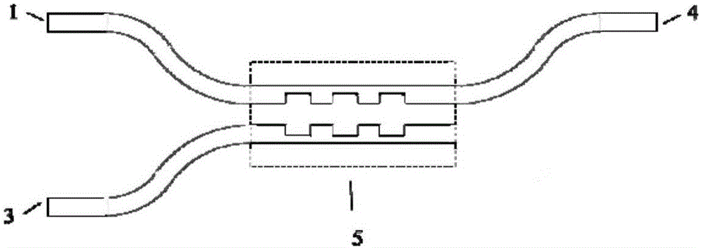
[0029] Such as image 3 As shown, this embodiment discloses a polarization beam splitter, including: a first input port 1 or a second input port 2 , a coupling region 5 , and a first output port 3 and a second output port 4 . It can be seen that the polarization beam splitter in this embodiment has one input port and two output ports.

[0030] The first input port 1 or the seco...


PUM


Abstract

The invention discloses a polarization beam splitter. The polarization beam splitter comprises a first input port 1 or a second input port 2, a coupling area 5, a first output port 3, and a second output port 4. The first input port 1 or the second input port 2 is connected with the input port of the coupling area 5, and the first output port 3 and the second output port 4 are connected with the output port of the coupling area 5. The coupling area 5 is formed by two adjacent optical waveguides, which are disposed in evanescent field ranges of waveguide modes of opposite sides. In the coupling area 5, grating structures of preset quantity are connected with the two waveguides, and are extended toward the outer sides of the two waveguides by preset lengths, and then a coupling length of a transverse electric wave TE is a half of a coupling length of a transverse magnetic wave TM. The polarization beam splitter provided by the invention is advantageous in that by adopting a function of gratings regulating and controlling a waveguide mode equivalent refractive index, an equivalent refractive index between the odd symmetric mode and the even symmetric mode of the TE is twice that of the TM, and the coupling length of the TE is a half of that of the TM, and therefore polarization beam splitting is realized.

Description

technical field [0001] The invention relates to the field of integrated optoelectronic devices, in particular to a polarization beam splitter. Background technique [0002] Since a silicon-on-insulator (Silicon-On-Insulator, SOI) platform has a relatively large refractive index difference, devices generally have polarization-sensitive characteristics. In order to solve this problem, a polarization diversity scheme is proposed. Among them, the polarizing beam splitter is a very important component. Researchers have proposed a variety of polarization beam splitter structures, including multimode-interference coupler, Mach-Zehnder interferometer, directional coupler, etc., and the directional coupling The solution of the device is widely used because of its simple structure and convenient design. Such as Figure 1a and Figure 1b Schematic cross-sections of the two directional coupler-based polarizing beam splitters shown, Figure 1a The medium polarization beam splitter us...

Claims


Application Information

Patent Timeline
IPC IPC(8): G02B6/126
CPCG02B6/126
Inventor 周治平刘璐
Owner PEKING UNIV
Learn More