Flame detection device and method based on plif technology
A flame detection device and flame technology, applied in the field of photoelectric analysis, can solve the problems of energy distribution divergence, large loss, unfavorable detection and analysis, etc., and achieve the effect of strong strength and improved precision
- Summary
- Abstract
- Description
- Claims
- Application Information
AI Technical Summary
Problems solved by technology
Method used
Image

Examples
Embodiment 1
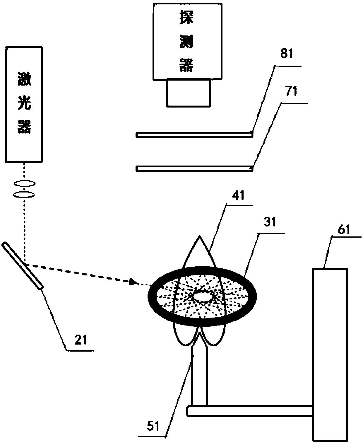
[0033] figure 1 Schematically provides the structure diagram of the flame detection device based on PLIF technology of the present embodiment, as figure 1 As shown, the flame detection device includes:
[0034] laser;
[0035] A light collimating device, such as a convex lens group, the light collimating device is fixed on the optical path of the outgoing light of the laser, and collimates the outgoing light;
[0036] A coupling module 21, such as a coupling mirror, which is used to couple the collimated outgoing light into the annular reflection pool;
[0037] An annular reflecting pool 31, the annular reflecting pool is arranged on the periphery of the flame, the outgoing light is reflected multiple times in the plane in the annular reflecting pool, and passes through the flame 41 repeatedly; the reflected light is all in one plane;
[0038] A moving unit 61, which moves the annular reflecting pool and the flame relatively, such as moving the nozzle 51 that generates the ...
Embodiment 2
[0049] The flame detection device based on PLIF technology of the present embodiment is different from Embodiment 1 in that:
[0050] 1. No longer use filter devices;
[0051] 2. The central normal line of the receiving surface of the detector such as ICCD coincides with the axis of the circular reflecting pool, and the plane where the reflected light of the circular reflecting pool is located is perpendicular to the axis of the flame, which minimizes the impact of the reflected light in the circular reflecting pool on detection influence of the device.
[0052] The flame detection method based on the PLIF technology of the embodiment of the present invention, that is, the working process of the above-mentioned flame detection device, the flame detection method includes the following steps:
[0053] (A1) The outgoing light emitted by the laser is coupled into the annular reflective pool;
[0054] (A2) The outgoing light is reflected back and forth in the plane in the annular...
Embodiment 3
[0058] The flame detection device based on PLIF technology of the present embodiment is different from Embodiment 1 in that:
[0059] 1. The collimated outgoing light is coupled into the optical fiber for transmission, and the light emitted from the optical fiber is coupled into the annular reflecting pool through the coupling device, and is reflected multiple times in the reflecting pool;
[0060] 2. The central normal line of the receiving surface of the detector such as ICCD coincides with the axis of the circular reflecting pool, and the plane where the reflected light of the circular reflecting pool is located is perpendicular to the axis of the flame, which minimizes the impact of the reflected light in the circular reflecting pool on detection influence of the device.
[0061] The flame detection method based on the PLIF technology of the embodiment of the present invention, that is, the working process of the above-mentioned flame detection device, the flame detection ...
PUM
 Abstract
Description
Claims
Application Information
 - R&D
- Intellectual Property
- Life Sciences
- Materials
- Tech Scout
- Unparalleled Data Quality
- Higher Quality Content
- 60% Fewer Hallucinations
Browse by: Latest US Patents, China's latest patents, Technical Efficacy Thesaurus, Application Domain, Technology Topic, Popular Technical Reports.
© 2025 PatSnap. All rights reserved.Legal|Privacy policy|Modern Slavery Act Transparency Statement|Sitemap|About US| Contact US: help@patsnap.com