Combined type intelligent electroslag system

A combined, electroslag technology, applied in furnace components, furnace cooling, lighting and heating equipment, etc., can solve the problems of inconvenient use of slag furnaces, increased production costs, low production costs, etc., and achieves ingenious structural design and improved The effect of production efficiency and strong applicability

Active Publication Date: 2016-11-09
TIANJIN CISRI HARDER MATERIALS & TECH
View PDF6 Cites 5 Cited by
  • Summary
  • Abstract
  • Description
  • Claims
  • Application Information

AI Technical Summary

Problems solved by technology

[0003] At present, the existing electroslag equipment is simple, with less investment and lower production costs. The disadvantage of electroslag remelting is high power consumption. The current general-purpose slag contains CaF 2 More, in the remelting process, it will pollute the environment, so dust removal and fluorine removal devices must be installed in the remelting process, which increases the production cost
[0004] In addition, most of the existing electroslag remelting uses liquid slag, which can reduce the point segregation at the bottom of the steel ingot, so a slag melting procedure is required before electroslag remelting, and most of the existing slag melting equipment is in the slag melting furnace carry out, and then pour the liquid slag into the crystallizer, the operation is very troublesome, in order to overcome the above-mentioned defects, the existing patent publication number is CN201924059U discloses a kind of electroslag remelting slag furnace, and the slag melting furnace publicly used can be more convenient Liquid slag is poured into the crystallizer, but it is extremely inconvenient to use the slag furnace when dumping, and there is still a risk of leakage when pouring, and the practicability is poor. Therefore, it is urgent to develop an intelligent control that can be used without dumping the slag furnace. Combined intelligent electroslag system for the remelting phase

Method used


Image

  • Combined type intelligent electroslag system
  • Combined type intelligent electroslag system
  • Combined type intelligent electroslag system

Examples


Embodiment 1

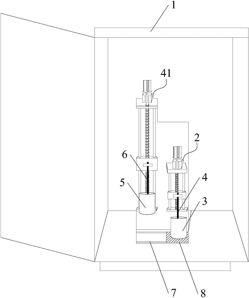
[0039] Such as figure 1 As shown, Embodiment 1 of the present invention provides a combined intelligent electroslag system, including a sealed box 1, which is used to fill inert gas, so that the electroslag process is completed under a protective atmosphere, making the steel ingot product more pure, In addition, the steelmaking process is completed in the sealed box 1, which can prevent CaF 2 Smoke is harmful to people, and it is safer and more environmentally friendly to use.

[0040] The sealed box 1 is provided with a slag removal assembly and a remelting assembly, and the slag removal assembly includes a slag removal pool 3, a lifting mechanism-2 and a slag removal electrode 4 connected to the lifting mechanism-2. The slag pool 3 is located below the slag removal electrode 4; the lifting mechanism-2 can drive the slag removal electrode 4 to move up and down. The slag constitutes an electrical connection path to carry out the slag removal process. The remelting assembly ...

Embodiment 2

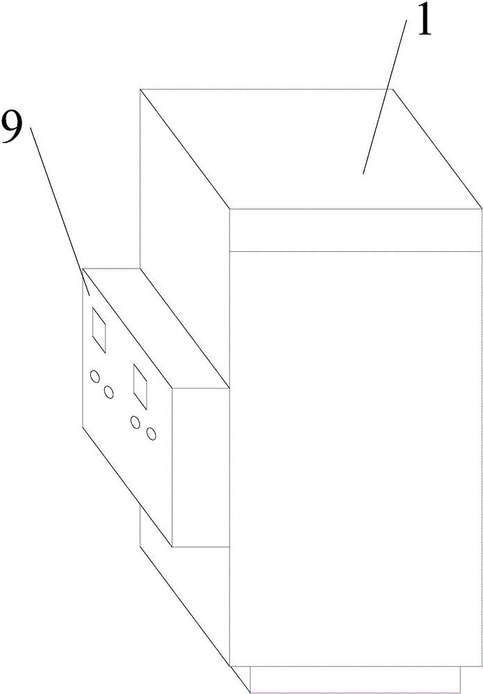
[0044] Such as figure 2 As shown, so the present invention also defines that the electroslag system also includes a controller 9, the controller 9 can realize the intelligent monitoring of the whole system, and the first lifting mechanism 2 and the second lifting mechanism 41 are connected with the controller 9 connection, the controller 9 is used to control the lifting of the first lifting mechanism 2 and the second lifting mechanism 41, so that the first lifting mechanism 2 and the second lifting mechanism 41 drive the slag slag electrode 4 and the second lifting mechanism respectively. The remelting electrode 6 moves up and down.

Embodiment 3

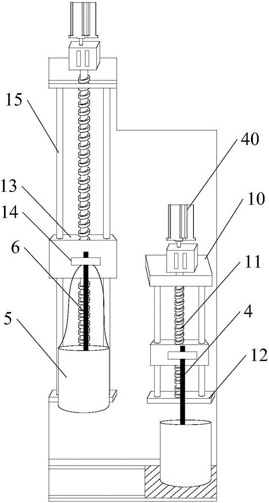
[0046] Embodiment 3 of the present invention provides a combined intelligent electroslag system. On the basis of Embodiment 2, the system further defines the structures of the first lifting mechanism 2 and the second lifting mechanism 41, which improves the practicability.

[0047] Such as image 3 As shown, it should be noted that the lifting mechanism 1 2 and the lifting mechanism 2 41 both include a support plate 10, a support plate 12 and a support plate fixed longitudinally between the support plate 10 and the support plate 2 12. Between the screw 11, the middle part of the support plate 10 and the support plate 12 has a through hole, the two ends of the screw 11 are connected in the through hole and pivotally connected with the through hole through the bushing or the bearing, that is to say, the screw The bar 11 can rotate relative to the first support plate 10 and the second support plate 12 . The top of the leading screw 11 is connected to the motor 40 connected to th...


PUM


Abstract

The invention provides a combined type intelligent electroslag system. The combined type intelligent electroslag system comprises a sealing box, wherein a slagging assembly and a remelting assembly are arranged in the sealing box; the slagging assembly comprises a slagging pond, a first lifting mechanism and a slagging electrode connected to the first lifting mechanism; the slagging pond is positioned below the slagging electrode; the remelting assembly comprises a crystallizer, a second lifting mechanism and a remelting electrode; the crystallizer and the remelting electrode are connected to the second lifting mechanism; the crystallizer is positioned below the remelting electrode. The electroslag system provided by the invention is skillful in structural design, and a controller automatically and intelligently controls the combined type intelligent electroslag system to finish slagging and remelting operations. The combined type intelligent electroslag system is convenient to use, and moreover, the labor cost is saved. The system is easy to disassemble and assemble, a steelmaking process is finished in the sealing box, and harm of CaF2 smoke to persons can be prevented. The combined type intelligent electroslag system is safe and environmentally friendly when used, and produced steel ingot products are pure.

Description

technical field [0001] The invention relates to the technical field of electroslag equipment, in particular to a combined intelligent electroslag system. Background technique [0002] The electroslag process generally means that molten slag is filled in a copper water-cooled crystallizer, and one end of the consumable electrode is inserted into the slag, and the consumable electrode, slag, metal molten pool, steel ingot, and bottom water tank are formed by short wires and transformers. In the circuit, during the power-on process, the slag emits Joule heat, which gradually melts the end of the consumable electrode, and the molten metal gathers into droplets, passes through the slag pool, falls into the crystallizer, and forms a molten metal pool. The metal droplets are cooled by water. Rapidly solidifies to form steel ingots. In the stage of the droplet formation at the electrode tip and the droplet dripping through the slag pool, the steel-slag is in full contact, the non-m...

Claims


Application Information

Patent Timeline
Patent Type & Authority Applications(China)
IPC IPC(8): F27B14/08F27B14/06F27B14/14F27D9/00F27B14/20C22B9/187
CPCC22B9/18F27B14/06F27B14/08F27B14/14F27B14/20F27D9/00F27D2009/0083
Inventor 王飞
Owner TIANJIN CISRI HARDER MATERIALS & TECH
Why Eureka
Try Eureka