
Device For The Emission Of Light In Particular For The Generation Of An Image

An image and display device technology, applied in the field of image-generating devices, can solve problems such as temperature rise and inability to export heat

Inactive Publication Date: 2016-11-09
VISTEON GLOBAL TECH INC
View PDF12 Cites 5 Cited by
  • Summary
  • Abstract
  • Description
  • Claims
  • Application Information

AI Technical Summary

Problems solved by technology

However, the heat emitted by the high-power LED cannot be completely dissipated by means of the heat sink arranged thermally coupled to the light-emitting element on the rear side, so that the temperature in the high-temperature region between the collimator lens and the display device rises sharply

Method used


Image

  • Device For The Emission Of Light In Particular For The Generation Of An Image
  • Device For The Emission Of Light In Particular For The Generation Of An Image
  • Device For The Emission Of Light In Particular For The Generation Of An Image

Examples


Embodiment Construction

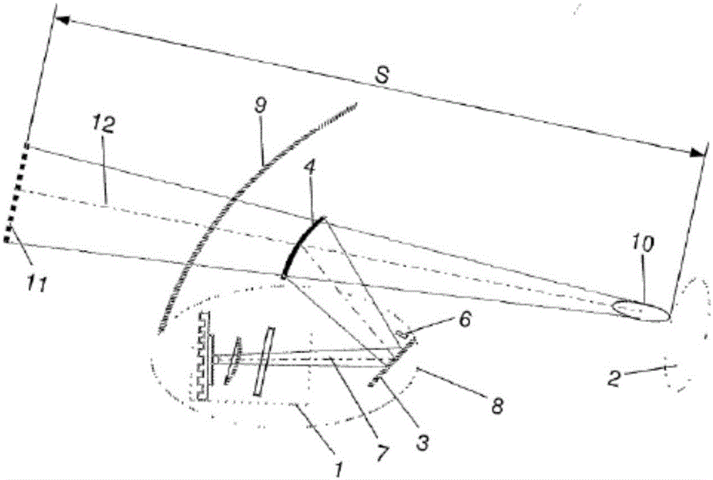
[0041] figure 1 A device 1 for lighting, in particular for generating a virtual image 11 , is shown within an assembly in a motor vehicle that has optical components for displaying information. The virtual image 11 is projected in the viewing direction of the driver 2 when looking through the windshield 9 in the direction of travel.

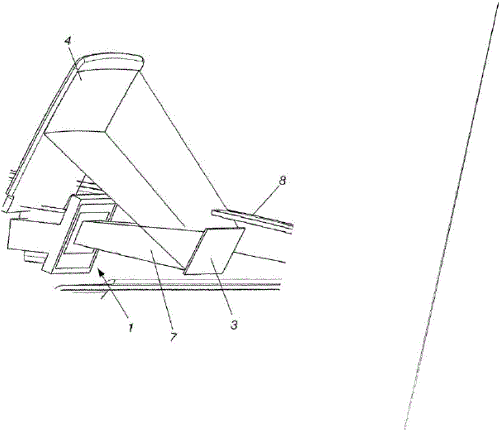
[0042]The device 1 and the optical components, in particular the first deflecting mirror 3 and the second deflecting mirror 4 , are arranged inside a dashboard 8 . The beam of light 7 emerging from the device 1 is conducted via the planar or aspherically convexly configured first deflecting mirror 3 to the aspherically concavely configured second deflecting mirror 4 . The light beam 7 exits the instrument panel 8 through a glare light trap, not shown. In combination with this glare light trap, a further light trap 6 arranged next to this glare light trap prevents the emission of light which would cause reflections and thus irritate the driver 2...


PUM


Abstract

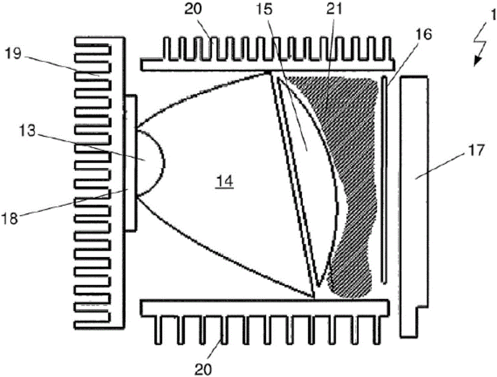
A device for the emission of light, in particular for the generation of an image, the device including at least one light source, at least one heat sink, a diffusor for diffusing and homogenizing the light emitted from the light source and comprises a thermal conduction device, is provided herein. The light source is constructed to be thermally coupled to a heat sink. The thermal conduction device is also constructed to be thermally coupled to a heat sink so that heat generated by the light source is transmitted to the thermal conduction device and from the thermal conduction device to the heat sink. The thermal conduction device is additionally constructed as a diffusor for diffusing and homogenizing the light emitted from the light source.

Description

technical field [0001] The invention relates to a device for emitting light, in particular for generating images. The device has at least one light source, at least one heat sink, a diffuser for scattering and homogenizing the light emitted by the light source, and heat conducting means. The light source is designed to be thermally coupled to the heat sink. Background of the invention [0002] Systems known from the prior art for generating images (also referred to as "picture generating units" or "image generating units" and abbreviated to PGU or IGU) are constructed with light-emitting diodes with increased power and illumination intensity as well as with There are specific lenses, especially collimating lenses. Systems for image generation by means of high-power light-emitting diodes (also referred to as high-power LEDs) are designed to increase the intensity of the display illumination and thus increase the intensity of the generated virtual images. [0003] The use o...

Claims


Application Information

Patent Timeline
Patent Type & Authority Applications(China)
IPC IPC(8): F21V29/70F21V29/71G02B27/01F21Y115/10
CPCF21V29/70F21V29/717G02B27/0101G03B21/16G03B21/208G02B6/0085G02B27/0149F21V29/50F21V29/505F21V29/506F21V29/508
Inventor D·安德烈耶夫
Owner VISTEON GLOBAL TECH INC
Learn More