Eureka AIR delivers breakthrough ideas for toughest innovation challenges, trusted by R&D personnel around the world.

Intelligent stage lamp

A stage light and intelligent technology, applied in the field of stage lights, can solve the problems of inconvenient maintenance and operation, complex structure of the whole machine, not beautiful appearance, etc., and achieve the effects of diversified installation and fixing methods, smaller size and beautiful appearance.

Active Publication Date: 2016-11-09
福建吉艾普光影科技有限公司
View PDF6 Cites 9 Cited by
  • Summary
  • Abstract
  • Description
  • Claims
  • Application Information

AI Technical Summary

Problems solved by technology

[0002] Most of the stage lighting structures basically have huge bases, arms, and heads. This structural design also directly leads to large volume, heavy body, difficult installation, high transportation costs, and inconvenient maintenance and operation. And other issues
At the same time, as lighting engineers pursue higher and higher stage effects, the light output effect of cylindrical products in the past can no longer meet their needs. The stage effect, the structure of the whole machine is complex and basically presents a circular appearance, inconvenient to use and not beautiful enough
[0003] The patent number is 201620230680.0, and the name is a practical LED pattern stage light, which includes a lamp head, a lamp arm and a bottom box connected sequentially from top to bottom. The lamp head is installed on the lamp arm through a lamp holder bracket. There is a rotatable connection between the lamp head and the lamp arm, and a rotatable connection between the lamp arm and the bottom box; In the internal space composed of the lamp housing and the upper housing of the lamp, there are focusing module, imaging lens, pattern module, color module, lens module, LED light source and heat dissipation module arranged sequentially from top to bottom; this technology is bulky and heavy , installation difficulties, high transportation costs, inconvenient maintenance and operation

Method used


Image

  • Intelligent stage lamp
  • Intelligent stage lamp
  • Intelligent stage lamp

Examples


specific Embodiment approach

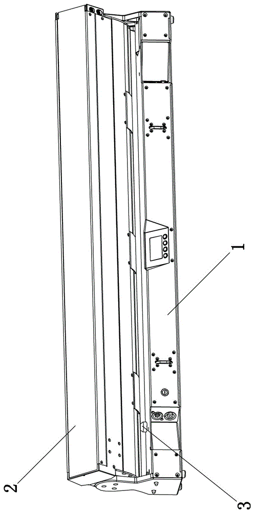
[0027] Such as figure 1 As shown, an intelligent stage light includes a base mechanism 1 and a light emitting mechanism 2 , the light emitting mechanism 2 is arranged on the base mechanism 1 , and the light emitting mechanism 2 is rotatable relative to the base mechanism 1 .

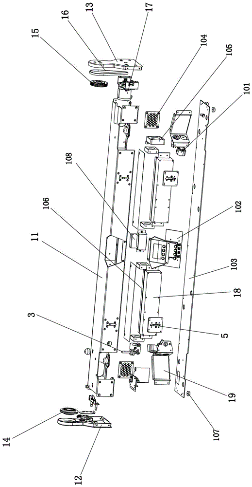
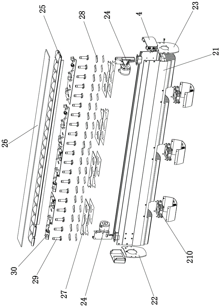
[0028] Such as figure 2 As shown, the base mechanism 1 of the present invention includes a bottom sheet metal 11, the left and right ends of the bottom sheet metal 11 are respectively connected with a left side cover 12 and a right side cover 13; the left side cover 12 is provided with a driven bearing 14 ; The right side cover 13 is provided with a driving gear 15; the driving gear 15 is connected with the drive shaft of the transmission motor 17 located on the bottom sheet metal 11 through a belt 16; the left and right sides of the bottom sheet metal 11 A power board 18 is respectively provided; the bottom sheet metal 11 is connected with a battery 108; the battery 108 is connected with the control p...


PUM


Abstract

The invention discloses an intelligent stage lamp which comprises a bottom metal plate and a light-emitting radiator. The left end and the right end of the bottom metal plate are connected with a left side cover and a right side cover correspondingly. A driven bearing is arranged on the left side cover, and a drive gear is arranged on the right side cover. The drive gear is connected with a driving shaft of a transmission motor. Power plates are arranged on the left side and the right side of the bottom metal plate correspondingly. A battery is connected to the bottom metal plate. A radiator is arranged at the back portion of each power plate. The left end and the right end of the light-emitting radiator are connected with a left connecting plate and a right connecting plate correspondingly. The left connecting plate is connected with the driven bearing, and the right connecting plate is connected with the drive gear. Lifting motor devices are arranged on the left side and the right side of the light-emitting radiator correspondingly. An LED driving power panel is arranged on the light-emitting radiator. According to the intelligent stage lamp, the speed is extremely high when the focal length of a lens is changed, the model is light and convenient to use, installation and fixation are convenient, rapidness is achieved, firmness and reliability are achieved, maintenance is convenient, the structural model of the whole stage lamp is more reasonable and attractive, and therefore the intelligent stage lamp can be used for setting a stage scene in a dot matrix configuration manner

Description

technical field [0001] The invention relates to the field of stage lights, in particular to an intelligent stage light. Background technique [0002] Most of the stage lighting structures basically have huge bases, arms, and heads. This structural design also directly leads to large volume, heavy body, difficult installation, high transportation costs, and inconvenient maintenance and operation. And other issues. At the same time, as lighting engineers pursue higher and higher stage effects, the light output effect of cylindrical products in the past can no longer meet their needs. The stage effect, the structure of the whole machine is complex and basically presents a circular appearance, which is inconvenient to use and not beautiful enough. [0003] The patent number is 201620230680.0, and the name is a practical LED pattern stage light, which includes a lamp head, a lamp arm and a bottom box connected sequentially from top to bottom. The lamp head is installed on the l...

Claims


Application Information

Patent Timeline
Patent Type & Authority Applications(China)
IPC IPC(8): F21S8/00F21V19/02F21V14/06F21V21/14F21V23/00F21W131/105F21W131/406F21Y115/10
CPCF21S8/00F21V14/06F21V19/02F21V21/14F21V23/003F21W2131/105F21W2131/406
Inventor 林啸白晓冬马福游广张
Owner 福建吉艾普光影科技有限公司
Why Eureka
Eureka Blog
Learn More