
Backlight module and display device

A technology of backlight module and light source, which is applied in the direction of lighting devices, fixed lighting devices, components of lighting devices, etc., which can solve the problems of reducing the applicability of display devices, reducing user experience, and display devices being unfavorable for multiple people to watch together. Achieve the effect of improving user experience and applicability

Active Publication Date: 2016-11-09
BOE TECH GRP CO LTD
View PDF5 Cites 9 Cited by
  • Summary
  • Abstract
  • Description
  • Claims
  • Application Information

AI Technical Summary

Problems solved by technology

[0003] At present, the method of reducing the light emitting angle of the backlight of the backlight module is often used to reduce the display viewing angle of the display device, so that the content displayed on the display device can only be seen by users within the range of the backlight emitting angle of the backlight module. Thereby reducing the probability that the displayed content is peeped by people around the user to protect the privacy of the user; however, when many people need to watch the displayed content together, the display device with a narrow display viewing angle is not conducive to many people watching together, thereby reducing the Show usability of the device and degrade user experience

Method used


Image

  • Backlight module and display device
  • Backlight module and display device
  • Backlight module and display device

Examples


Embodiment 1

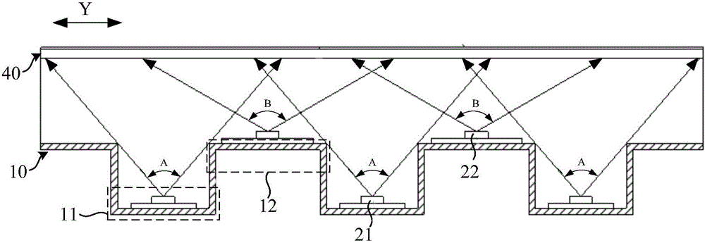
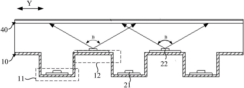
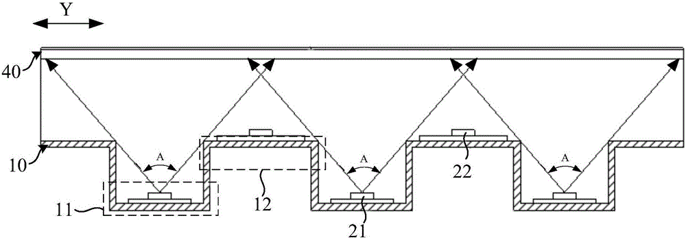
[0043] This embodiment provides a backlight module, see figure 1 as shown, figure 1 It is a cross-sectional view of the backlight module along the direction from any concave part to a convex part adjacent to it, and the backlight module includes:

[0044] The back plate 10 is formed with a plurality of concave parts 11 and raised parts 12 which are alternately distributed in sequence; in specific implementation, the back plate 10 can be made of sheet metal, and the depressed parts 11 and raised parts 12 can be stamped Method preparation;

[0045] A plurality of first light sources 21, each first light source 21 is correspondingly installed in a recessed portion 11, and the light output direction of each first light source 21 faces the opening of the corresponding recessed portion 11;

[0046] A plurality of second light sources 22, each second light source 22 is correspondingly installed on a raised portion 12, and is located on the side of the raised portion 12 away from th...

Embodiment 2

[0075] This embodiment provides a display device, including the above-mentioned backlight module.

[0076] In this display device, the back plate 10 of its backlight module includes a plurality of recessed parts 11 and raised parts 12 that are distributed alternately in sequence. The shading of the recessed portion 11 has an included angle A smaller than the light emitting angle of the first light source 21, and since the outgoing light of the second light source 22 is not blocked, the included angle A of the light emitted by the first light source 21 from the recessed portion 11 is smaller than the first light source 22. The light output angle of the second light source 22; during the use of the display device, when it is necessary to realize normal viewing angle display, the first light source 21 is controlled to be closed and the second light source 22 is turned on. Since the outgoing light of the second light source 22 is not blocked, At this time, the backlight module can...


PUM


Abstract

The invention relates to the technical field of display, and discloses a backlight module and a display device. The backlight module comprises a back plate, a plurality of first light sources and a plurality of second light sources, wherein a plurality of concave parts and convex parts which are alternately distributed in sequence are formed on the back plate; each first light source is mounted in the corresponding concave part, and the light emitting direction of each first light source faces the opening of the corresponding concave part; each second light source is mounted on the corresponding convex part and located on the side, away from the corresponding concave part, of the convex part, and the light emitting direction of each second light source is identical with that of the corresponding first light source; and in the arrangement direction of the concave parts and the convex parts, the included angle of light, emitted from the corresponding concave part, of each first light source is smaller than the light emitting angle of the first light sources and the light emitting angle of the second light sources. The backlight emitting angle of the backlight module is adjustable, so that the display view angle of the display device adopting the backlight module is adjustable, and the applicability of the display device and the use experience of users are improved.

Description

technical field [0001] The invention relates to the field of display technology, in particular to a backlight module and a display device. Background technique [0002] With the development of science and technology, computers and mobile terminals (such as mobile phones and tablet computers) have been widely used in office and study fields. When a user uses a computer or a mobile terminal in a public place, the content displayed on the display device may be peeped by people around the user, thereby causing the risk of leakage of private information of the user. [0003] At present, the method of reducing the light emitting angle of the backlight of the backlight module is often used to reduce the display viewing angle of the display device, so that the content displayed on the display device can only be seen by users within the range of the backlight emitting angle of the backlight module. Thereby reducing the probability that the displayed content is peeped by people aroun...

Claims


Application Information

Patent Timeline
IPC IPC(8): F21S8/00F21V14/02F21V17/10F21V19/02F21Y115/10
CPCF21S8/00F21V14/02F21V17/104F21V19/02
Inventor 胡楠楠王鑫杨凡
Owner BOE TECH GRP CO LTD
Learn More