Eureka AIR delivers breakthrough ideas for toughest innovation challenges, trusted by R&D personnel around the world.

Positioning socket type pipe joint structure

A pipe joint and socket-type technology, which is applied in the field of pipe joints, can solve the problems of collision between the end of the socket and the bottom of the socket, wear of the end of the socket and the bottom of the socket, shortening the service life of the pipe, etc., to simplify the construction of the socket Requirements, eliminate wear or damage, and improve the effect of construction progress

Inactive Publication Date: 2016-11-09
闫莉
View PDF9 Cites 3 Cited by
  • Summary
  • Abstract
  • Description
  • Claims
  • Application Information

AI Technical Summary

Problems solved by technology

During the insertion process, the depth of the socket inserted into the socket is not easy to grasp, and the collision between the end of the socket and the bottom of the socket is prone to occur, resulting in wear and tear on the end of the socket and the bottom of the socket, and even damage to the anti-corrosion layer, shortening the service life of the pipeline
In order to avoid the occurrence of the above phenomenon, the plugging process needs to be carried out carefully, and this will easily affect the construction progress, delay the construction period and increase the construction cost

Method used


Image

  • Positioning socket type pipe joint structure

Examples


Embodiment Construction

[0020] It should be noted that, in the case of no conflict, the embodiments of the present invention and the features in the embodiments can be combined with each other.

[0021] In describing the present invention, it should be understood that the terms "center", "longitudinal", "transverse", "upper", "lower", "front", "rear", "left", "right", " The orientations or positional relationships indicated by "vertical", "horizontal", "top", "bottom", "inner" and "outer" are based on the orientations or positional relationships shown in the drawings, and are only for the convenience of describing the present invention and Simplified descriptions, rather than indicating or implying that the device or element referred to must have a particular orientation, be constructed and operate in a particular orientation, and thus should not be construed as limiting the invention. In addition, the terms "first", "second", etc. are used for descriptive purposes only, and should not be understood ...


PUM


Abstract

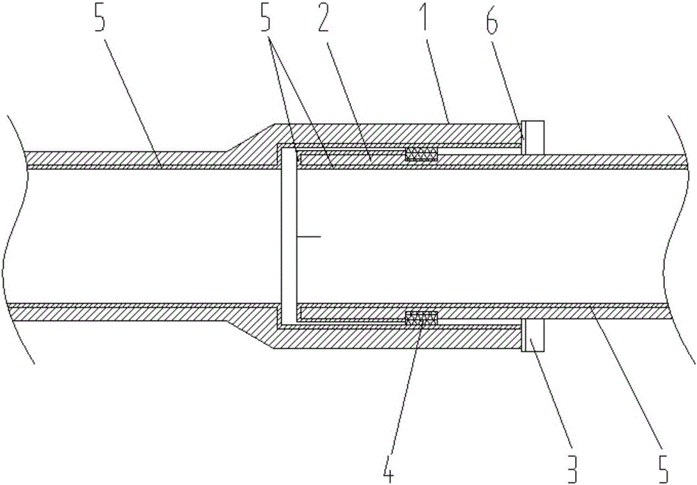
The invention discloses a positioning socket type pipe joint structure. The structure comprises a bearing port and an inserting port in insertion matching of pipe fittings; a sealing ring is arranged between the bearing port and the inserting port; a positioning ring is peripherally arranged on the outer wall of the pipe fitting near the inserting port; the outer diameter of the positioning ring is larger than the inner diameter of the bearing port; and the distance from the end part of the inserting port to the positioning ring is smaller than the depth of the bearing port. When multiple pipe fittings are connected end to end to form the pipe, as the positioning ring is arranged on the outer wall of the pipe fitting near the inserting port, the collision phenomenon between the end part of the inserting port and the bottom of the bearing port caused by deep insertion in the inserting port has no need to worry about, the insertion construction requirements can be simplified to a certain extent, and the purposes of accelerating the connecting speed of the pipe fittings, accelerating the construction progress, shortening the construction period and saving the construction cost are achieved; and meanwhile, the wear or damage phenomenon of the inner walls of the pipe fittings and corrosion-resistant layers caused by collision between the end part of the inserting port and the bottom of the bearing port is eliminated, so that the normal service life of the pipe is guaranteed.

Description

technical field [0001] The invention relates to the field of pipe joints, in particular to a positioning socket type pipe joint structure. Background technique [0002] When the socket-type pipe fittings are connected into pipelines, the socket of the pipe fittings to be connected is inserted into the socket of the pipe fittings to be connected, and the sealing and anti-slip between the pipe fittings to be connected are realized through the sealing ring arranged between the socket and the socket. During the insertion process, the depth of the socket inserted into the socket is not easy to grasp, and the collision between the end of the socket and the bottom of the socket is prone to occur, resulting in wear and tear on the end of the socket and the bottom of the socket, and even damage to the anti-corrosion layer, shortening the service life of the pipeline. In order to avoid the occurrence of the above phenomenon, the plugging process needs to be carried out carefully, whic...

Claims


Application Information

Patent Timeline
Patent Type & Authority Applications(China)
IPC IPC(8): F16L21/02
CPCF16L21/022
Inventor 闫莉
Owner 闫莉
Why Eureka
Eureka Blog
Learn More