
Novel drilling mud pump

A drilling mud, a new type of technology, applied in the direction of pumps, multi-cylinder pumps, piston pumps, etc., can solve the problems of reducing transmission efficiency and working reliability, increasing pump volume and weight, and increasing the weight of mud pumps. It achieves compact structure, Effect of reducing maintenance cost and reducing mass

Active Publication Date: 2016-11-09
SHANDONG HI-SPEED KERUI PETROLEUM EQUIP CO LTD
View PDF7 Cites 16 Cited by
  • Summary
  • Abstract
  • Description
  • Claims
  • Application Information

AI Technical Summary

Problems solved by technology

The traditional mud pump mainly has the following disadvantages: 1. The number of cylinders is small. The traditional mud pump is mainly three cylinders. The phase difference of the mud pump in this structure is 120°, and the displacement fluctuates greatly. Poor, in order to enhance the rigidity and strength, the diameter of the crankshaft needs to be increased, resulting in an increase in the weight and volume of the mud pump
2. The transmission mode is unreasonable. The traditional mud pump mainly uses the motor to drive the gear shaft through the intermediate transmission mode. The small gear of the gear shaft meshes with the large gear of the crankshaft to transmit the power to the crankshaft. The transmission chain is long and the mechanical loss is large, which reduces the transmission efficiency and work. reliability, while increasing the volume and weight of the pump, it is not easy to move quickly, and it is difficult to adapt to offshore drilling platforms and other occasions with special requirements for floor space

Method used


Image

  • Novel drilling mud pump
  • Novel drilling mud pump
  • Novel drilling mud pump

Examples


Embodiment Construction

[0022] The present invention will be further described below in conjunction with the accompanying drawings.

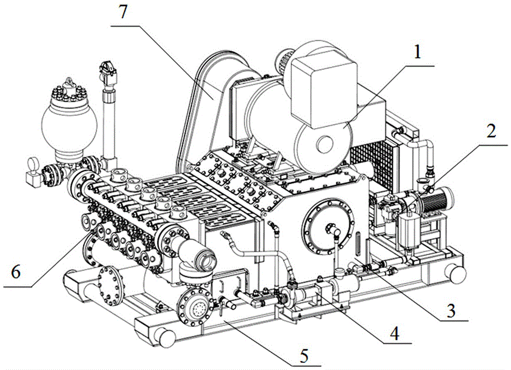
[0023] see Figure 1-4 , a new type of drilling mud pump, a new type of drilling mud pump, the base 5 is sequentially installed with a hydraulic end assembly 6, a power end assembly 3 and a lubrication system 2 from front to back.

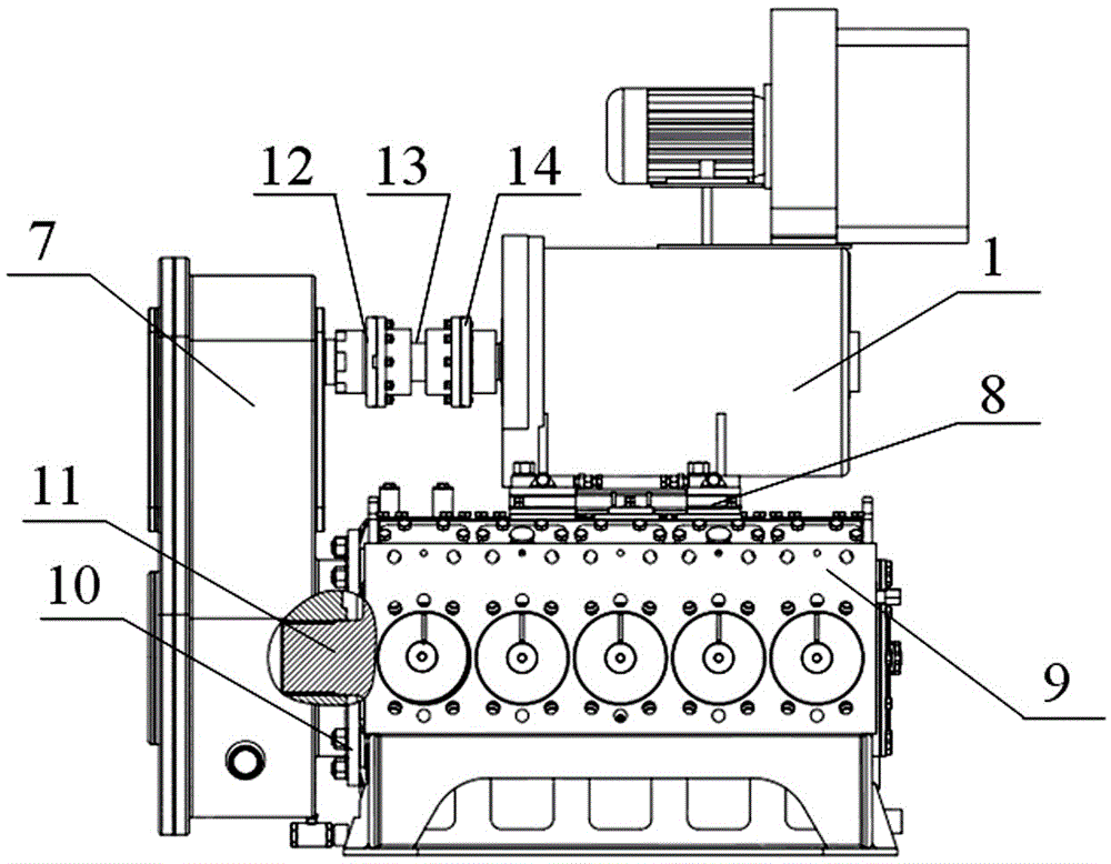
[0024] The power end assembly 3 includes a driving motor 1, a gear reduction box 7, and a crankshaft 11, a connecting rod 15 and a crosshead 19 installed in the pump casing 9; the driving motor 1 is an AC variable frequency motor, which can realize stepless speed regulation, and through The motor installation base 8 is installed on the top of the pump casing 9, and the gear reduction box 7 is installed on one side of the pump casing 9; the output end of the driving motor 1 passes through the motor output flange 14, the spherical cage synchronous coupling 13, and the input of the reduction box in sequence. The flange 12 is connected to the ...


PUM


Abstract

The present invention discloses a novel drilling mud pump which is a five-cylinder single-acting piston pump, comprising: a base; and a power end assembly, a hydraulic end assembly, a lubricating system and a spraying system that are mounted on the base; the power end assembly is in transmission connection with the hydraulic end assembly; the lubricating system is a forced lubricating system for a lubricating pump set; the spraying system is used for cooling a piston in a cylinder sleeve. The novel drilling mud pump is large in displacement, small in size, light in weight, compact in structure and reliable in operation and is convenient to assemble and disassemble; the traditional three-cylinder mode is replaced with a five-cylinder mode, liquid flow pulsation rate is decreased, and displacement is increased; a transmission scheme of an alternating-current variable frequency motor with a gear reducer box is used in connection with alternating-current variable frequency technology, transmission efficiency is improved, and pump efficiency is given to full play; a hydraulic end pump head is of split structure, reducing the usage and maintenance cost of the pump; a power end linkage is of sliding bearing structure, reducing the size of the pump and reducing its weight.

Description

technical field [0001] The invention relates to the field of oil drilling and production equipment, in particular to a drilling mud pump for oil and natural gas development. Background technique [0002] In the drilling industry, the drilling mud pump is known as the "heart" of the drilling rig. It mainly plays the role of cooling the drill bit, pumping high-pressure drilling fluid, removing cuttings from the bottom of the well, dealing with complex downhole conditions and controlling pressure. The performance of the drilling mud pump is good. Deterioration has a direct impact on drilling rates and costs. With the development of oil and natural gas exploitation, the drilling depth continues to deepen, and the traditional mud pump has become a bottleneck restricting the development of drilling equipment. The traditional mud pump mainly has the following disadvantages: 1. The number of cylinders is small. The traditional mud pump is mainly three cylinders. The phase differenc...

Claims


Application Information

Patent Timeline
Patent Type & Authority Applications(China)
IPC IPC(8): F04B1/00F04B15/02F04B9/02F04B17/03F04B53/08F04B53/18F04B53/00
CPCF04B1/00F04B9/02F04B15/02F04B17/03F04B53/00F04B53/08F04B53/18
Inventor 尹沿林张聍薛建刚赵富于海华
Owner SHANDONG HI-SPEED KERUI PETROLEUM EQUIP CO LTD
Learn More