Eureka AIR delivers breakthrough ideas for toughest innovation challenges, trusted by R&D personnel around the world.

Cooling, conveying and cutting device for eraser strip

A cutting device, cooling and conveying technology, applied in metal processing and other directions, can solve the problems of aging of electrical components, rubber strip breaking or accumulation, slow cooling speed, etc., to achieve the effect of efficient shearing, preventing deformation, preventing fracture or accumulation

Active Publication Date: 2016-11-09
宿州市超晟文具有限公司
View PDF5 Cites 4 Cited by
  • Summary
  • Abstract
  • Description
  • Claims
  • Application Information

AI Technical Summary

Problems solved by technology

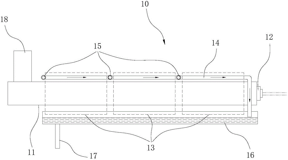
[0002] The rubber processing technology generally includes processes such as raw material mixing, granulation, coloring, extrusion, and shearing. The rubber processing equipment in the prior art often has the following defects: 1. The cooling speed is relatively slow after the extruder stops, which is easy to cause damage to electrical appliances. The components are aging, and it is not convenient for equipment maintenance; 2. The rubber strip extruded by the extruder has a slow curing speed, and it is easy to deform during the transportation process, which affects product quality; 3. The traction speed of the rubber strip traction device cannot be adjusted in real time, which may easily lead to The rubber strip is broken or piled up; 4. The rubber strip lacks a limit guide device, and it is easy to shift during the transportation process

Method used


Image

  • Cooling, conveying and cutting device for eraser strip
  • Cooling, conveying and cutting device for eraser strip
  • Cooling, conveying and cutting device for eraser strip

Examples


Embodiment Construction

[0015] The present invention will be described in detail below with reference to the accompanying drawings.

[0016] In the description of the present invention, it should be noted that the terms "upper", "lower", "left", "right", "inner", "outer", etc. indicate the orientation or positional relationship based on the drawings. The orientation or positional relationship is only for the convenience of describing the present invention and simplifying the description, rather than indicating or implying that the device or element referred to must have a specific orientation structure and operation, and therefore cannot be understood as a limitation of the present invention.

[0017] A rubber processing system, including:

[0018] The extruder 10, the extruder 10 includes a screw conveyor 11, the discharge end of the screw conveyor 11 is provided with an extrusion port 12, the outer wall of the screw conveyor 11 is provided with a heating jacket 13 and a cooling water pipe 14, the extruder...


PUM


Abstract

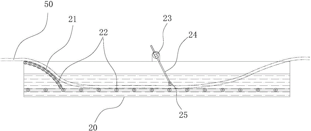
The invention belongs to the field of eraser production and processing and particularly relates to a cooling, conveying and cutting device for an eraser strip. The cooling, conveying and cutting device comprises a cooling water tank and a cutting device body, wherein the cooling water tank is arranged along an extrusion opening of an extruder in an extension mode and filled with cooling water; the eraser strip extruded by the extruder enters the cooling water tank, so that cooling and hardening of the eraser strip are accelerated; after being cooled in the cooling water tank, the eraser strip enters the cutting device body; the cutting device body comprises a fodder chopper and an intermittent feeding mechanism; the fodder chopper moves back and forth in the vertical direction and is matched with a workbench to do a shearing action for cutting the eraser strip; and the intermittent feeding mechanism can convey the eraser strip to the position below the fodder chopper in an intermittent mode, specifically, when the fodder chopper is lifted, the eraser strip is fed forwards, and when the fodder chopper falls, the eraser strip is stopped being fed. According to the cooling, conveying and cutting device for the eraser strip, the extruded eraser strip can be rapidly cooled and cured through the cooling water tank, and deformation is prevented; and the eraser strip can be efficiently sheared through the cutting device body, so that breaking or stacking of the eraser strip is prevented.

Description

Technical field [0001] The invention belongs to the field of rubber production and processing, and specifically relates to a rubber strip cooling, conveying and cutting device. Background technique [0002] Rubber processing technology generally includes raw material mixing, granulation, coloring, extrusion, shearing, etc. The rubber processing equipment in the prior art often has the following defects: 1. After the extruder is stopped, the cooling rate is slow, which is easy to cause electrical appliances. The components are aging and it is not easy to maintain the equipment; 2. The rubber strip extruded by the extruder has a slow curing speed, which is easy to deform during the conveying process, which affects the product quality; 3. The traction speed of the rubber strip traction device cannot be adjusted in real time, which is easy to cause The rubber strip is broken or piled up; 4. The rubber strip lacks a limit guide device, which is prone to offset during the conveying pro...

Claims


Application Information

Patent Timeline
Patent Type & Authority Applications(China)
IPC IPC(8): B29C47/88B29C47/34B29C47/00B26D1/08B29C48/355
CPCB26D1/085B29C48/0022B29C48/355B29C48/9135B29C48/919
Inventor 刘双超
Owner 宿州市超晟文具有限公司
Why Eureka
Eureka Blog
Learn More