Electric planer

An electric planer, the technology on the other side, applied in the direction of manual planing, processing machines for manufacturing flat surfaces, wood processing appliances, etc., can solve the problems of complex structure, low adaptability, etc. long effect

Active Publication Date: 2016-11-09
李俊
View PDF13 Cites 0 Cited by
  • Summary
  • Abstract
  • Description
  • Claims
  • Application Information

AI Technical Summary

Problems solved by technology

[0002] Application No. 94244067.6 is a multifunctional portable electric planer for planing, cutting, chamfering, sanding, drilling, cutting stones or metal products. The fastening end cover is made, the fastening end cover and the motor bearing end face are on the same plane, parallel to each other and the other end is fixed. The transmission shaft is connected to each functional assembly by plug-in type, and the functional assembly has a conical square concave hole One end is inserted into the end of the conical square shaft of the drive shaft, the other end is inserted into the inner diameter of the inner bearing of the fastening end cover, and the fastening end cover is fixed with a threaded rod. The structure is complex and the scope of application is low.

Method used


Image

  • Electric planer
  • Electric planer
  • Electric planer

Examples


Embodiment 1

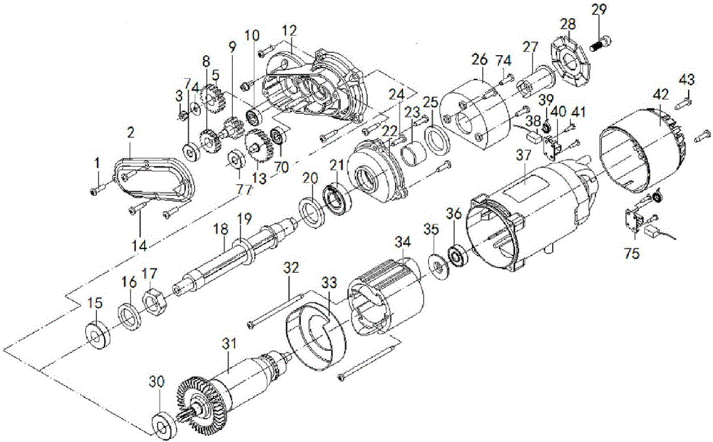
[0031] Embodiment 1: as figure 1 , figure 2 , image 3 , Figure 4 , Figure 5 , Image 6 , Figure 7 , Figure 8 As shown, an electric planer, the front cover 2 is connected to the gear box 12 through the cross pan head screw 1 and the cross pan head self-tapping screw 14, and the secondary cutter shaft gear 5 is connected to the gear box 12 through the nut 3 and the gasket 4. The inner cavity is connected, one side of the middle pinion 9 is connected with the first bearing 7 and the middle plate tooth 8, the other side of the middle pinion 9 is connected with the second bearing 10, and the outer circumferences of the second bearing 10 and the fourth bearing 70 are respectively connected The inner cavity of the gear box 12, the outer circumferences of the first bearing 7 and the third bearing 77 are respectively connected to the inner cavity of the front cover 2, one side of the first-stage large gear 13 is connected to the third bearing 77, and the other side of the f...

Embodiment 2

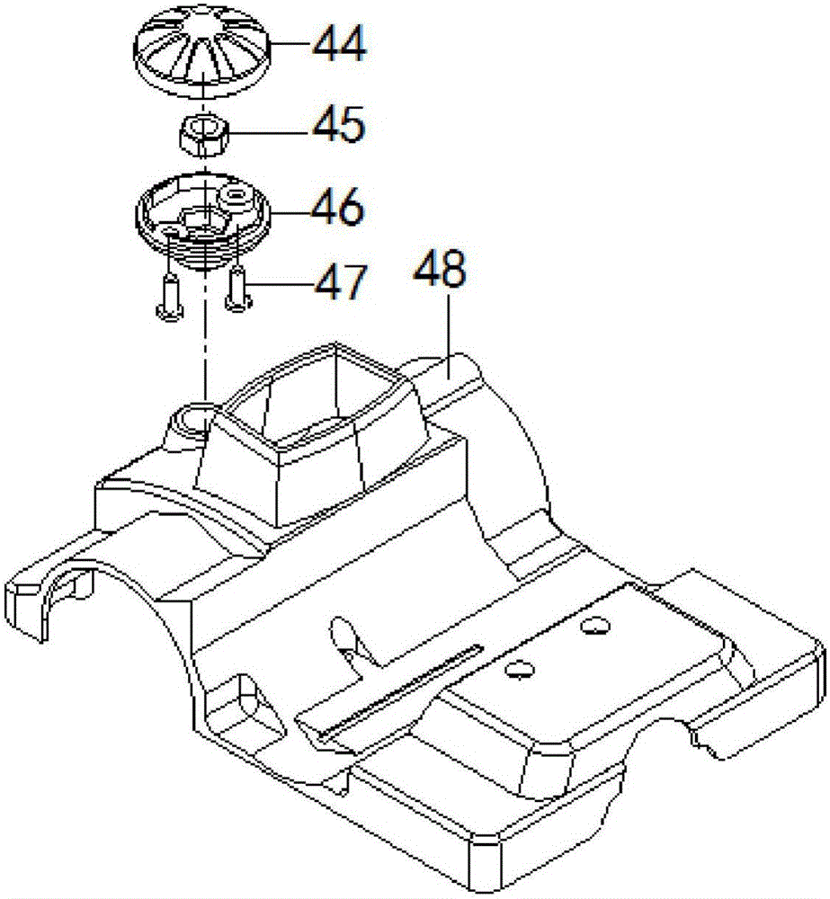
[0033] Embodiment 2: as figure 1 , figure 2 , image 3 , Figure 4 , Figure 5 , Image 6 , Figure 7 , Figure 8 , Figure 9 As shown, an electric planer, the adjustable structure of the bottom plate adopts double springs and single screws to expand and contract, and the rear screw is used for positioning, which makes the adjustment more balanced, and the adjustment size is enlarged. Changing the original single spring positioning balance is easy to fail.

[0034] like Figure 9 , Figure 10 As shown, the cutter shaft 18 is connected to the wall scraping tool, the rust removal tool and the irregularly dislocated special-shaped knife, and the wall scraping tool is an irregularly dislocated special-shaped knife 80; Figure 11 As shown, the derusting tool adopts a circular wire structure; Figure 12 As shown, the irregularly dislocated special-shaped knife is adopted, and the outer circumference of the knife holder 82 of the irregularly dislocated special-shaped knife...


PUM


Abstract

The invention discloses an electric planer and belongs to the technical field of tools. A third bearing is connected to one side of a first-stage large gear; the other side of the first-stage large gear is connected with a fourth bearing; a rotor is engaged with the first-stage large gear which is engaged with middle flat plate teeth; the middle flat plate teeth are coaxial with a middle small gear; the middle small gear is engaged with a second-stage knife shaft gear; a double-spring and single-screw telescopic structure is adopted for a bottom plate adjustable structure which is positioned through a rear screw; a depth adjusting bolt is fixed to a bottom plate; a depth adjusting spring is arranged between a base and the bottom plate; and a depth adjusting frame is connected with a depth button. The electric planer has the beneficial effects that the gears are adopted for transmitting power, the service life is long, slip is avoided, a double-spring type structure is adopted for a lifting structure, lifting balance performance is better, an operator can perform adjustment through an automatic handle lifting structure, and the hand feeling of the operator is better.

Description

technical field [0001] The invention relates to an electric planer, which belongs to the technical field of tools. Background technique [0002] Application No. 94244067.6 is a multifunctional portable electric planer for planing, cutting, chamfering, sanding, drilling, cutting stones or metal products. The fastening end cover is made, and the fastening end cover and the motor bearing end face are on the same plane, parallel to each other. The other end is fixed. One end is inserted into the end of the conical square shaft of the drive shaft, the other end is inserted into the inner diameter of the inner bearing of the fastening end cap, and the fastening end cap is fixed with a threaded rod. The structure is complex and the scope of application is low. Contents of the invention [0003] In order to overcome the deficiencies of the prior art, the invention provides an electric planer. [0004] An electric planer, one side of the first-stage large gear is connected to the...

Claims


Application Information

Patent Timeline
Patent Type & Authority Applications(China)
IPC IPC(8): B27C1/10B27C1/14
CPCB27C1/10B27C1/14
Inventor 李俊
Owner 李俊
Why Eureka
Try Eureka