Eureka AIR delivers breakthrough ideas for toughest innovation challenges, trusted by R&D personnel around the world.

Device for high-frequency induction brazing machine

A high-frequency induction brazing and basic block technology, applied in auxiliary devices, welding equipment, auxiliary welding equipment, etc., can solve the problems of inability to guarantee the quality of aircraft parts, inaccurate positioning of aircraft parts, and threats to the lives of operators, and achieve savings. The effect of clamping time, shortening welding time and ensuring welding quality

Active Publication Date: 2016-11-09
SHAANXI AIRCRAFT CORPORATION
View PDF5 Cites 7 Cited by
  • Summary
  • Abstract
  • Description
  • Claims
  • Application Information

AI Technical Summary

Problems solved by technology

Flame brazing can only clamp aircraft parts one at a time, resulting in low production efficiency
Moreover, the positioning of aircraft parts is not accurate, and the quality of aircraft parts after welding cannot be guaranteed. At the same time, the environment of this welding method is poor. During welding, the operator is close to the flame injection area for a long time, which poses a great threat to the life of the operator.

Method used


Image

  • Device for high-frequency induction brazing machine
  • Device for high-frequency induction brazing machine
  • Device for high-frequency induction brazing machine

Examples


Embodiment 1

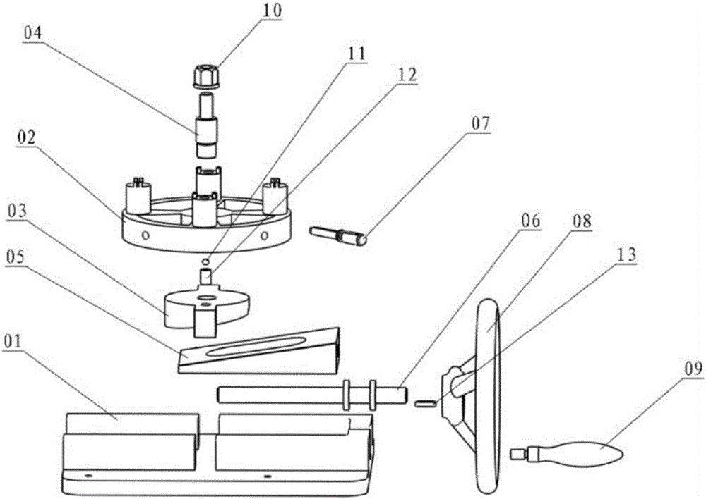
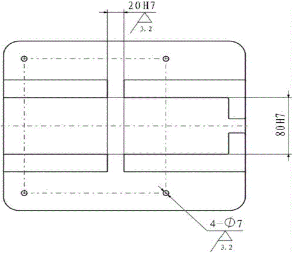
[0036]The U-shaped groove of 80H7 on the basic block 01 is used as the chute of the wedge-shaped block 05. The U-shaped groove can limit the movement of the wedge-shaped block 05 along the length direction of the upper surface of the basic block 01. The chute of the block 03, the elongated through groove can limit the lifting movement of the slider 03 along the height direction of the cuboid of the basic block 01;

Embodiment 2

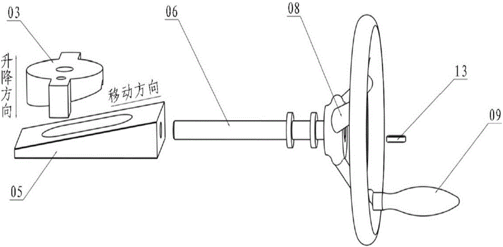
[0038] After the round wheel handle 08, the curved surface handle 09, the ordinary flat key 13, the screw 06, and the wedge block 05 are connected, by rotating the curved surface handle 09, the round wheel handle 08 is driven to rotate, and the screw 06 is rotated together, and the wedge block 05 is on the screw 06 Driven by the drive, it can reciprocate on the base block 01; the slope of the wedge block 05 exerts force on the slope of the slider 03, so that the protrusion of the slider 03 moves along the rectangular parallelepiped in the elongated slot of the base block 01. The height direction is lifted and lowered, and finally the positioning seat 02 connected with the slider 03 is lifted along the height of the 20H7 long slot on the basic block 01, that is, the height direction of the basic block 01 cuboid, and the lifting range is 0 ~ 10mm. This range value is determined according to the height of the working table of the high-frequency induction welding machine from the c...


PUM


Abstract

The invention discloses a device for a high-frequency induction brazing machine and belongs to the technical field of process equipment for aircraft part welding. According to the technical scheme of the device, a clamp main body part of the device is connected with the high-frequency induction brazing machine, rising and falling of a locating seat is achieved ultimately through a rotary curved handle, and then by rotating the locating seat, a cylinder convex block on the locating seat is located in a correct position during wielding of the high-frequency induction brazing machine. The device has the advantages that welding of aircraft parts is conducted on the device for the high-frequency induction brazing machine through the high-frequency induction brazing machine, four to-be-welded aircraft parts can be clamped at one time, clamping time is saved, meanwhile, welding time is shortened, and thus the production efficiency is improved. Locating is conducted through the cylinder convex block on the locating seat of the device, and thus welding quality of the aircraft parts can be ensured effectively. Due to the fact that ceramic is selected and used as the materials of the locating seat, the life safety of operating workers during welding is further improved.

Description

technical field [0001] The invention relates to a device for a high-frequency induction brazing machine, which belongs to the technical field of aircraft parts welding process equipment. Background technique [0002] At present, the company uses flame brazing, which mainly uses the flame of combustible gas mixed with oxygen or compressed air as the heat source to weld the product parts. Flame brazing can only clamp aircraft parts one at a time, resulting in low production efficiency. Moreover, the positioning of aircraft parts is not accurate, and the quality of aircraft parts after welding cannot be guaranteed. At the same time, the environment of this welding method is poor. During welding, the operator is close to the flame injection area for a long time, which poses a great threat to the life of the operator. Contents of the invention [0003] Purpose of the invention: the present invention provides a device for welding aircraft parts on a high-frequency induction bra...

Claims


Application Information

Patent Timeline
IPC IPC(8): B23K1/002B23K3/00B23K3/08B23K37/04
CPCB23K1/002B23K3/00B23K3/087
Inventor 肖望东黄蓉王声王俊李翀韩波
Owner SHAANXI AIRCRAFT CORPORATION
Why Eureka
Eureka Blog
Learn More