Device and method for generating uniform and continuous discharge or plasma photonic crystals
A plasma and photonic crystal technology, which is applied in the field of plasma application technology and optics, can solve the problems of inconvenient control of photonic crystal parameters, difficult to precisely control the propagation of electromagnetic waves, complex structure, etc., and achieves easy large-scale industrial application and high economy. , the effect of reducing production costs
- Summary
- Abstract
- Description
- Claims
- Application Information
AI Technical Summary
Problems solved by technology
Method used
Image
Examples
Embodiment 1
[0039] Embodiment 1, a device capable of generating uniform continuous discharge or plasma photonic crystal.
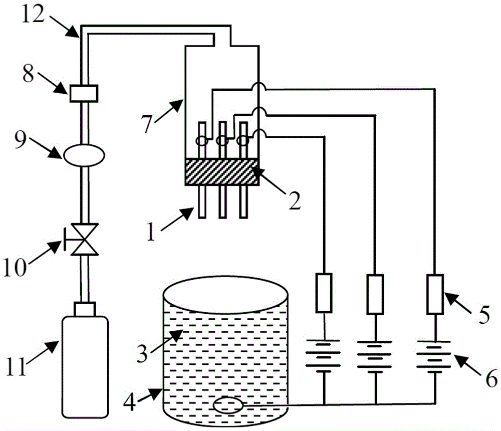
[0040] Such as figure 1 As shown, the device provided by the present invention includes a discharge mechanism, an air supply mechanism and a power supply mechanism.
[0041] The discharge mechanism in this embodiment includes three hollow needle electrodes 1 , a dielectric block 2 and a liquid electrode 3 . Three hollow needle electrodes 1 are vertically connected on the dielectric block 2 at equal intervals side by side, and the upper and lower ends of the hollow needle electrodes 1 are exposed outside the dielectric block 2. The material of the dielectric block 2 can be rubber or polytetrafluoroethylene, etc. . The material of the hollow needle electrode 1 can be metal materials such as tungsten, copper or iron; the inner diameter of the hollow needle electrode 1 is 0.5-2mm, which can be selected according to the specific needs. The lower end of the hollow needle...
Embodiment 2
[0047] Embodiment 2, a method for generating uniform and continuous discharge.
[0048] The devices used in the method for generating uniform and continuous discharge in this embodiment are as described in Embodiment 1.
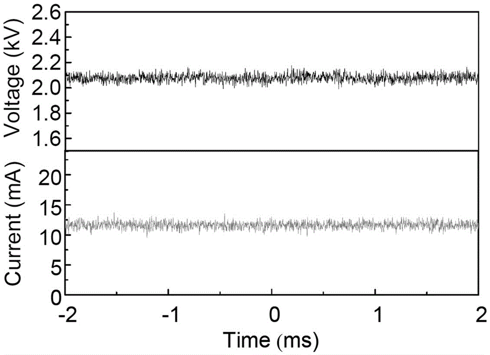
[0049] First follow figure 1 Connect the parts as shown. The dielectric tube 7 used in this embodiment has a length of 10 cm and an inner radius of 1 cm. The inner diameters of the three hollow needle electrodes 1 inserted on the dielectric block 2 are all 0.5 mm, and the distance between two adjacent hollow needle electrodes 1 is 5 mm. Both the upper end and the lower end of the hollow needle electrode 1 are exposed 2 cm outside the dielectric block 2 . The liquid contained in the open container 4 is tap water, the open container 4 is a beaker with an inner radius of 4 cm, and the horizontal plane of the liquid electrode 3 is circular. The material of the dielectric block 2 is rubber, and the material of the dielectric tube 7 is glass. The three high-vo...
Embodiment 3
[0053] Embodiment 3, a method for producing plasmonic photonic crystals.
[0054] This embodiment is carried out on the basis of embodiment 2. In this embodiment, the argon gas is contained in the gas cylinder 11, and the gas valve 10 is opened, so that the argon gas in the gas cylinder 11 enters the hollow needle electrode 1 through the gas supply pipeline 12 and the dielectric tube 7, and is discharged from the hollow needle electrode 1. The lower end sprays out. Plasma photonic crystals can be generated between the discharge end of the hollow needle electrode 1 and the level of the liquid electrode 3 . The flow rate of argon gas passed into the dielectric tube 7 is controlled at 4 L / min by a flow meter 8 .
[0055] The discharge photo of the plasma photonic crystal produced by argon gas in this embodiment is as follows Figure 4 shown. It can be seen that three periodically arranged plasmonic columns can be generated between the discharge end of the hollow needle electr...
PUM
| Property | Measurement | Unit |
|---|---|---|
| Resistance | aaaaa | aaaaa |
| The inside diameter of | aaaaa | aaaaa |
Abstract
Description
Claims
Application Information
 - Generate Ideas
- Intellectual Property
- Life Sciences
- Materials
- Tech Scout
- Unparalleled Data Quality
- Higher Quality Content
- 60% Fewer Hallucinations
Browse by: Latest US Patents, China's latest patents, Technical Efficacy Thesaurus, Application Domain, Technology Topic, Popular Technical Reports.
© 2025 PatSnap. All rights reserved.Legal|Privacy policy|Modern Slavery Act Transparency Statement|Sitemap|About US| Contact US: help@patsnap.com


