Printing screen and method for imaging a printing screen

A printing screen and imaging technology, which is applied in printing, printing machines, printing processes, etc., can solve the problems of low stability and expensive manufacturing of fine mesh screen materials

Inactive Publication Date: 2018-08-03
GALLUS FERD RUESCH
View PDF8 Cites 0 Cited by
  • Summary
  • Abstract
  • Description
  • Claims
  • Application Information

AI Technical Summary

Problems solved by technology

This fine mesh wire mesh material is more expensive to manufacture and less stable

Method used


Image

  • Printing screen and method for imaging a printing screen
  • Printing screen and method for imaging a printing screen
  • Printing screen and method for imaging a printing screen

Examples


Embodiment Construction

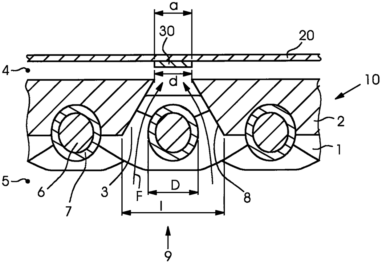
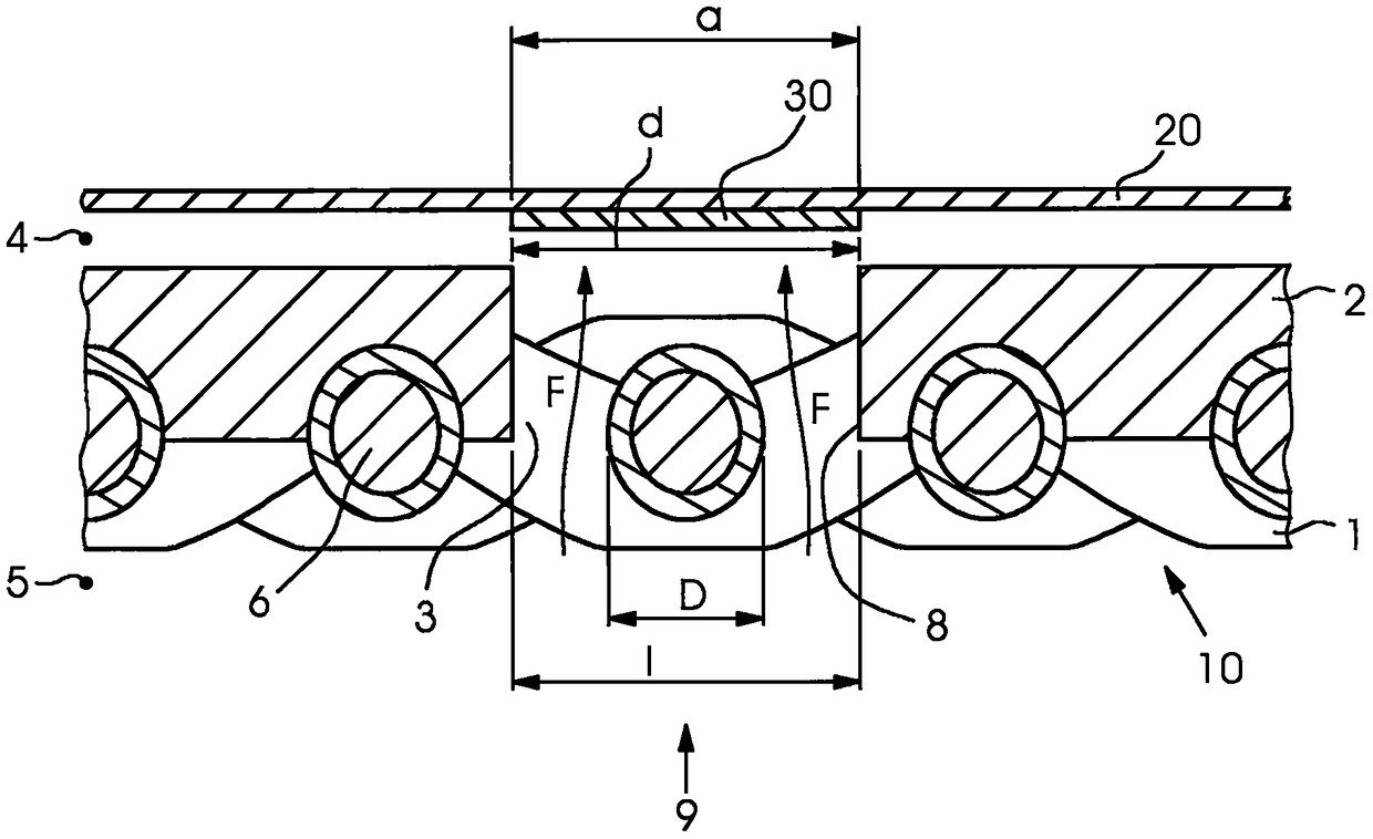
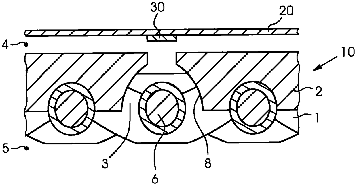
[0040] Figure 6 A flat screen material 10 with a fabric layer 1 according to the prior art is shown. On one side, the screen material 10 has a photopolymer coating 2 (direct stencil). In an alternative embodiment not shown, an imaged film may be applied to the screen structure 10 (indirect stencil). The nickel-plated flat screen material 10 consists of a fabric 1 . Different forms of fabric, also called fabric types, are possible.

[0041] This type of screen material 10 and the printing screen 10 of the present invention are used in rotary screen printing: Figure 7 A screen 100 is shown comprising a flat screen material 10 formed to create a cylindrical sleeve for rotary screen printing. The mesh material 10 retains its cylindrical shape by end pieces not shown in any detail. A squeegee of an invisible screen printing unit is provided inside the screen 100 to squeeze ink through the screen material 10 . The scrapers may be oriented parallel to the axis of rotation of ...


PUM


Abstract

The invention relates to a printing screen with at least one screen-like fabric layer (1) as a carrier structure with fabric threads (6) oriented at an angle to one another and with an imaged stencil layer ( 2), wherein the stencil layer (2) and the fabric layer (1) are connected to each other, and the stencil layer (2) is provided with channels (3). According to the invention, each channel (3) has a smaller opening (9) on the printing material side (4) of the printing screen (10) than on the squeegee side (5) of the printing screen (10), and each The channel forms a continuous channel. Such a printing screen (10) has sufficient stability and advantageously allows printing of very fine lines and dots. The invention also relates to methods for imaging such printing screens.

Description

technical field [0001] The invention relates to a printing screen for screen printing processes having the features described in the preamble of claim 1 . Background technique [0002] The industrial use of screens and fabrics is known in many fields. [0003] Screens used for screening purposes usually have square mesh openings. This mesh shape has also been used in the printing industry. With existing photosensitive layers and known application methods, acceptable image resolution can only be achieved with a large number of "supports". This is why the use of high mesh fabrics is becoming more and more common. [0004] The field of printed electronics requires the use of the thinnest possible screens or fabrics made of the thinnest possible threads to provide smooth flow of paste and to enable printing of very complex images. [0005] The field of coating solar cells, i.e. metallized solar cells, requires the application of large amounts of paste and very precise and hi...

Claims


Application Information

Patent Timeline
Patent Type & Authority Patents(China)
IPC IPC(8): B41F15/34B41N1/24B41C1/14H05K3/12
CPCB41C1/145B41F15/0881B41F15/36B41F15/38B41N1/248B41N1/243B41N1/247
Inventor H·布罗克H-R·弗里克M·罗森费尔德
Owner GALLUS FERD RUESCH
Why Eureka
Try Eureka