
Crop greenhouse climate control system

A technology for climate control and crops, applied in control/regulation systems, climate change adaptation, non-electric variable control, etc., can solve problems such as complex wiring, system collapse, and inconsistent system control actions

Inactive Publication Date: 2018-02-13
延川县创新机械制造有限责任公司
View PDF6 Cites 0 Cited by
  • Summary
  • Abstract
  • Description
  • Claims
  • Application Information

AI Technical Summary

Problems solved by technology

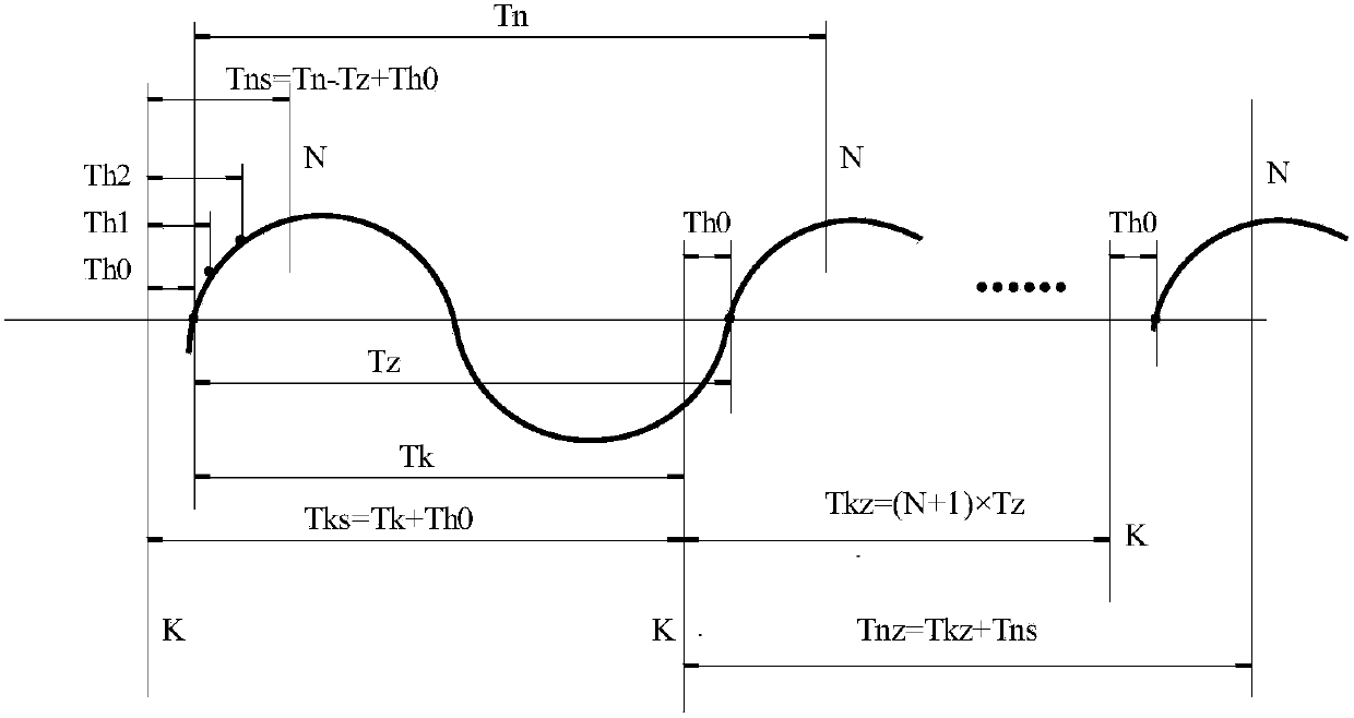
Due to the use of dedicated line communication, the wiring is complicated and the cost is increased. If the timing time is not corrected through the line communication, due to the traditional timing error, after several hours of operation, the accumulated timing error will make the system control action inconsistent, which may cause the system to collapse. In some occasions where the design is changed frequently and the amount of wiring engineering is large, the product application is limited

Method used


Image

  • Crop greenhouse climate control system
  • Crop greenhouse climate control system
  • Crop greenhouse climate control system

Examples


Embodiment Construction

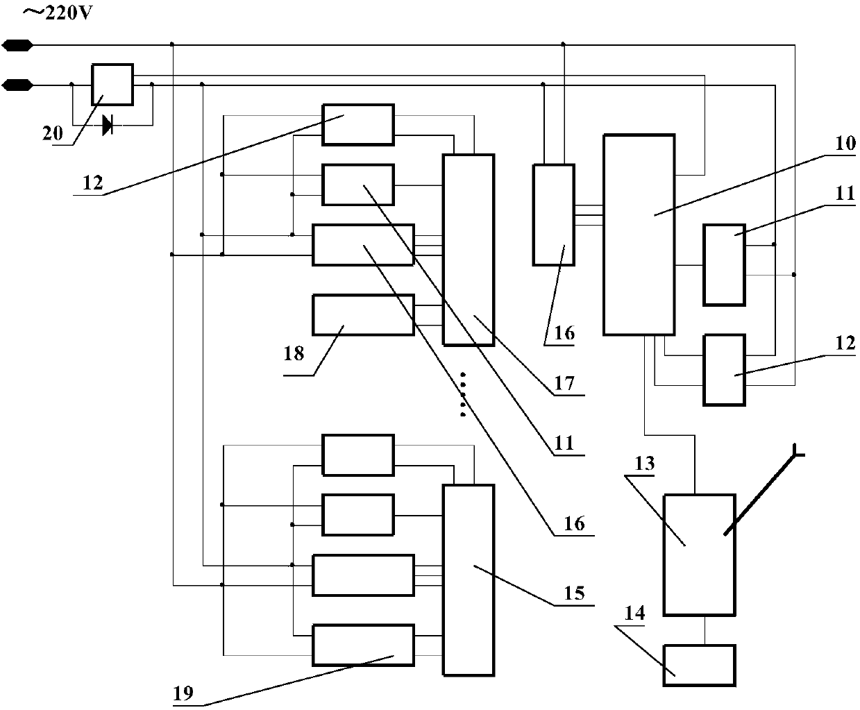
[0030] image 3 It is a block diagram of the circuit structure of the crop greenhouse climate control system, including: main controller (10), communication electronic switch (11), switch drive module (12), mobile phone short message sending and receiving device (13), SIM card (14), electrical controller (15), cycle discrimination circuit (16), data collector (17), temperature and humidity sensor (18), electrical equipment (19), electronic switch (20). Among them, the communication electronic switch (11), the switch drive module (12), the frequency discrimination circuit (16) and figure 2 The single-chip microcomputer (U0) is included in the electrical appliance controller (15), the data collector (17) and the main controller (10), and the electronic switch (20) and the communication electronic switch (11) use bidirectional thyristors as switches .

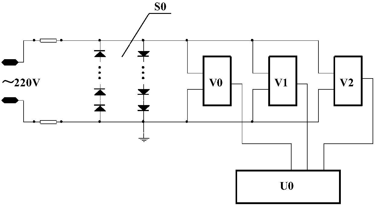
[0031] figure 2 It is a structural diagram of the cycle discrimination circuit (16), which is composed of: input circuit (S0)...


PUM


Abstract

The invention relates to a crop greenhouse climate control system, comprising a plurality of data acquisition devices, a plurality of electrical appliance controllers and a main controller, wherein the main controller contacts an owner via a GSM (Global System for Mobile Communications) network. The outputs of the electrical appliance controllers are serially connected to a power supply of furnace or pump electrical appliance equipment under the control of a photoelectric isolator, a two-way controlled silicon controller or a relay contact circuit, and the power-on power and time of loads of the electrical appliance controllers are thus controlled.

Description

(1) Technical field: [0001] The invention relates to a climate control system for a greenhouse of crops, which comprises a plurality of data collectors, a plurality of electrical controllers and a main controller, and the main controller communicates with the owner through the GSM network. The output of the electrical appliance controller is controlled by photoelectric isolation, bidirectional thyristor control or relay contact circuit, and connected in series to the power supply of furnace and pump electrical equipment to control its load power and time. (two) background technology: [0002] In the control system that is powered by the power grid, each electronic device or module communicates through a dedicated line to correct the timing time of each electronic device or electronic module to achieve the purpose of synchronous operation. Due to the use of dedicated line communication, the wiring is complicated and the cost is increased. If the timing time is not corrected t...

Claims


Application Information

Patent Timeline
Patent Type & Authority Patents(China)
IPC IPC(8): G05D27/02A01G9/24
CPCA01G9/24G05D27/02Y02A40/25
Inventor 张金木
Owner 延川县创新机械制造有限责任公司
Learn More