Projector and optical engine module

A technology for optical machine modules and projectors, which is applied to optics, instruments, and color TV parts, etc., can solve the problems of increasing the volume of the projector, reducing the service life of the light valve, and excessive noise, achieving good heat dissipation effects and improving use The effect of improving the lifespan and improving the cooling efficiency

Active Publication Date: 2018-03-27
CORETRONIC
View PDF5 Cites 0 Cited by
  • Summary
  • Abstract
  • Description
  • Claims
  • Application Information

AI Technical Summary

Problems solved by technology

However, this will greatly increase the size of the projector and generate excessive noise
In addition, only installing a heat dissipation module at the rear end of the light valve without effectively cooling the front end of the light valve will cause an excessive temperature difference between the front end of the light valve and the rear end of the light valve, resulting in unexpected internal stress, making the use of the light valve Reduced lifespan

Method used


Image

  • Projector and optical engine module
  • Projector and optical engine module
  • Projector and optical engine module

Examples


Embodiment Construction

[0024] The aforementioned and other technical contents, features and effects of the present invention will be clearly presented in the following detailed description of multiple embodiments with reference to the accompanying drawings. The directional terms mentioned in the following embodiments, such as up, down, front, back, left, right, etc., are only directions referring to the drawings. Accordingly, the directional terms are used to illustrate, not to limit, the invention.

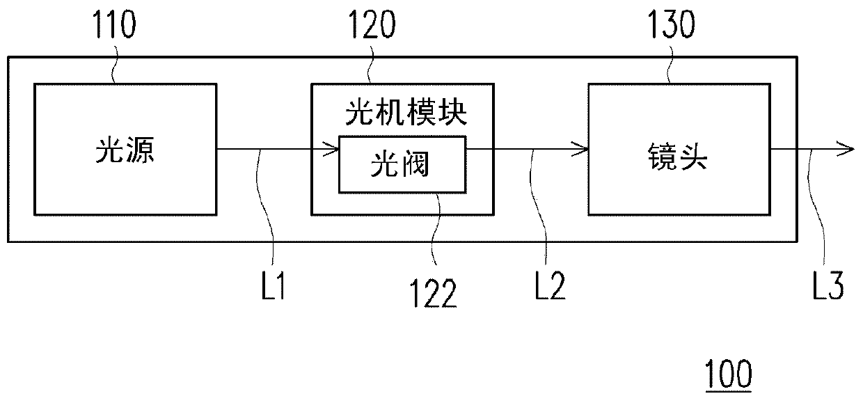
[0025] figure 1 is a schematic block diagram of a projector according to an embodiment of the present invention. Please refer to figure 1 , the projector 100 of this embodiment includes a light source 110 , an optical-mechanical module 120 and a lens 130 . The light source 110 is used to generate an illumination light beam L1. The light source module 110 includes, for example, at least one of a light emitting diode, a laser source, a high-pressure mercury lamp, a solid-sate light source, or other s...


PUM


Abstract

A projector includes a light source, an optical engine module, and a projection lens. The light source is configured for providing an illumination beam. The optical engine module includes a light valve, a casing, and a heat conducting structure. The light valve is configured to convert the illumination beam into an image beam. The light valve has a front portion and a rear portion opposite to each other. The casing is connected to the front portion. The heat conducting structure is disposed on the casing and at at least one side of the front portion. The projection lens is disposed on the casing and configured to project an image. The heat conducting structure is configured to dissipate heat of the casing and the front portion of the light valve.

Description

technical field [0001] The present invention relates to an optical device and an optical module, and in particular to a projector and an optical machine module. Background technique [0002] The projector uses a light valve to convert the illumination beam from the light source into an image beam, and uses a projection lens to convert the image beam into a projection beam and project it out. As the projection brightness of the projector increases, the heat generated when the light valve acts increases correspondingly. In order to prevent the light valve from overheating, the heat dissipation efficiency of the light valve will be improved by increasing the volume of the heat dissipation module and the speed of the heat dissipation fan. However, this will greatly increase the size of the projector and generate excessive noise. In addition, only installing a heat dissipation module at the rear end of the light valve without effectively cooling the front end of the light valve...

Claims


Application Information

Patent Timeline
Patent Type & Authority Patents(China)
IPC IPC(8): G03B21/20G03B21/16
CPCH04N9/3144G03B21/16H04N9/3197
Inventor 侯凯伦陈德堂简暐珉
Owner CORETRONIC
Why Eureka
Try Eureka