A connection system and construction method of combined shear wall

A shear wall and system technology, applied to walls, building components, earthquake resistance, etc., can solve problems such as hard to repair, spalling, concrete cracking, etc., and achieve the effects of reducing construction waiting time, saving construction period, and facilitating construction operations

Active Publication Date: 2017-05-03
CHONGQING YUFA CONSTR
View PDF3 Cites 0 Cited by
  • Summary
  • Abstract
  • Description
  • Claims
  • Application Information

AI Technical Summary

Problems solved by technology

However, the composite steel truss coupled shear wall still has the following disadvantages due to the use of the traditional coupling beam structure system: the coupling beam is rigidly connected to the steel column, and the coupling beam is subjected to bending and shearing forces at the same time, which are transmitted to the concrete, resulting in joint area (The connection point between the coupling beam and the steel column) The concrete is severely cracked or even peeled off; the separate setting of each coupling beam (construction floor, generally 1 to 3 floors) will cause serious local damage to each floor (construction floor), which is difficult to repair
The mechanical system of the combined rectangular beam-column frame and the combined shear wall structure of this structure is essentially different and has the following defects: First, the application range of the built-in steel truss concrete combined rectangular beam-column frame is limited, and it is only suitable for The closed structure of the beam-column frame or the beam-column frame structure in the shape of a space cylinder is adopted, and then the steel truss is built in the shear wall of the frame structure, and then the bearing capacity of the beam is improved by using the built-in steel truss, so as to prevent The role of premature yielding of beams, and at the same time improve the structural stability, and the application range of combined shear walls is larger and more extensive, because the structural stress system of combined shear walls is not necessarily spatially cylindrical Or limit the closed connection of the wall; the second is that the structural force system of the composite shear wall and the force system of the beam-column frame structure do not belong to the same kind of building structure force system, and there is a clear difference, because the scope of application of the frame structure Narrower, even the combined rectangular beam-column frame with built-in steel truss is only used in ordinary high-rise buildings, while the combined shear wall is mainly used in the earthquake resistance of super high-rise buildings.
[0007] To sum up, at present, it is still impossible to effectively overcome the problem of coupling beams in the composite combined shear wall structure system at home and abroad. Effectively overcome the technical defects of the current coupling beams subjected to bending and shearing during earthquakes

Method used


Image

  • A connection system and construction method of combined shear wall
  • A connection system and construction method of combined shear wall
  • A connection system and construction method of combined shear wall

Examples


Embodiment 1

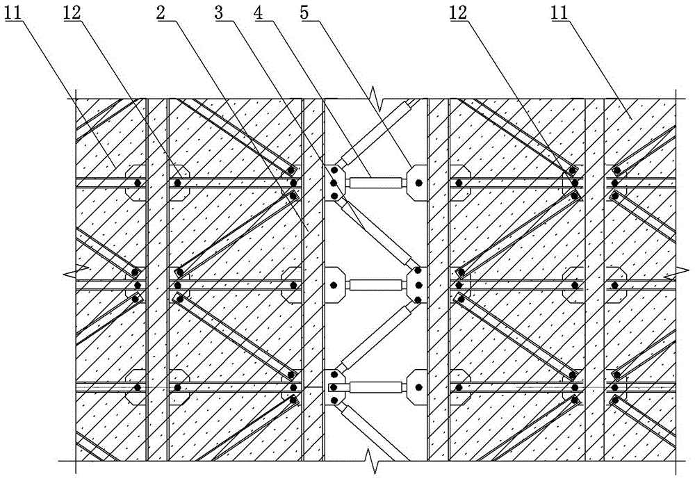
[0049] Example as figure 1 , figure 2 , image 3 , Figure 4 Shown: a connection system for a composite shear wall, including a shear wall limb 11 with a built-in steel truss 12, a steel bone column 2, and an exposed web member. The connecting plate 5 is fixedly connected along the length direction of the steel column 2, and the exposed web and the built-in steel truss 12 are respectively hinged with the connecting plate 5, and the steel column 2, the exposed web and the built-in steel truss 12 are combined to form an integral steel frame. For the truss, the steel bone column 2 serves as the chord of the overall steel truss, and the exposed web serves as the web of the overall steel truss. The steel column 2 is arranged inside the shear wall pier 11 as an outer frame column. The connecting plate 5 can be welded with the steel frame column 2, or can be bolted with the steel frame column 2, etc. In this embodiment, the connecting plate 5 is welded with the steel frame colum...

Embodiment 2

[0057] The applicant also invented another new type of safety telescopic rod for the connection system of combined limb shear walls. The safety telescopic rod includes a hollow sleeve rod 82 and a threaded rod 83 made of high-strength structural steel. Such as Figure 5 As shown, the right end of the hollow sleeve rod 82 is welded with a connector 61, the hollow sleeve rod 82 is formed with a hollow cavity arranged axially along the hollow sleeve rod 82, and the left side wall of the hollow cavity is provided with a The internal thread of the hollow cavity is smooth on the right side. The threaded rod 83 is screwed into the hollow cavity inside the hollow sleeve rod 82 . A piston 84 is mounted on the right end of the threaded rod 83, and the piston 84 is slidingly engaged with the left side wall of the hollow cavity. The piston 84 and the hollow cavity form a closed pressure chamber 85 , the pressure chamber 85 is filled with hydraulic oil, and the pressure chamber 85 is als...


PUM


Abstract

The invention particularly discloses a connecting system of hybrid coupled shear wall. The connecting system comprises exposed web members and adjacent shear wall limbs, built-in steel trusses and steel columns are arranged in the shear wall limbs, and the steel columns are fixedly connected with connecting plates; the two ends of each exposed web member are fixedly connected with the connecting plates on the steel column arranged in the shear wall limb adjacent to the exposed web member, the steel columns, the exposed web members and the built-in steel trusses are combined into an integral steel truss through the connecting plates. The connecting system effectively solves the technical problems existing at present, the exposed web members and the built-in steel trusses of the shear wall limbs are combined, therefore, the technical defect that an existing connecting beam is subjected to a bend shear effect in an earthquake is eliminated, modularized construction of the hybrid coupled shear wall becomes possible, and not only is the construction cycle effectively shortened, but also construction cost is reduced.

Description

technical field [0001] The invention relates to the technical field of combined limb shear walls, in particular to a connection system and construction method of combined limb shear walls. Background technique [0002] The combined shear wall structure is a lateral force-resistant system that combines two or more reinforced concrete shear walls to resist horizontal loads through connecting beams, because of its high lateral stiffness and redundancy of bearing capacity, etc. It has become one of the forms commonly used in the structure of high-rise buildings (especially super high-rise buildings above 300 meters) in China. Combined shear walls resist horizontal loads through a dual mechanism. Different from the ordinary shear wall which only relies on the plastic hinge energy consumption at the bottom of the shear wall, the rationally designed combined shear wall conforms to the principle of multiple seismic defense lines. The steel coupling beam as the first defense line fi...

Claims


Application Information

Patent Timeline
Patent Type & Authority Patents(China)
IPC IPC(8): E04B2/56E04B2/58E04B1/98E04H9/02
CPCE04B2/56E04B2/58E04H9/021
Inventor 高峰伍云天梅凤德李龙
Owner CHONGQING YUFA CONSTR
Why Eureka
Try Eureka