A waterproof knob switch

A technology of knob switch and switch, which is applied in the direction of electric switches, electrical components, circuits, etc., can solve the problem of high safety performance, and achieve the effect of high safety, not easy to damage and aging

Active Publication Date: 2018-03-06
台州小眼睛科技有限公司
View PDF6 Cites 0 Cited by
  • Summary
  • Abstract
  • Description
  • Claims
  • Application Information

AI Technical Summary

Problems solved by technology

[0005] The purpose of the invention is to solve the problem of liquid or water vapor contacting the circuit in the switch, and to provide a waterproof knob switch, which is waterproof and not easy to be affected by moisture and aging, and has high safety performance

Method used


Image

  • A waterproof knob switch
  • A waterproof knob switch
  • A waterproof knob switch

Examples


Embodiment 1

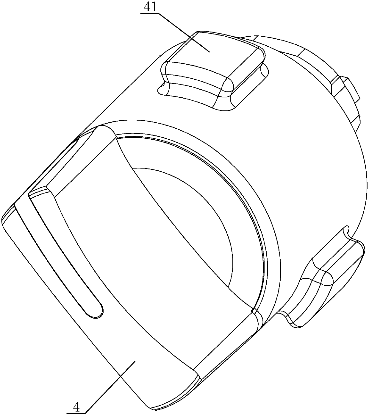
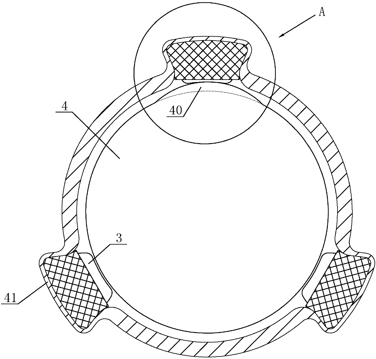
[0035] like Figures 1 to 9 The shown waterproof knob switch includes a housing and a knob 4, and the knob 4 is sleeved on the inner wall of the housing. The switch cavity 41 is provided with three trigger switch assemblies. The trigger switch assemblies are evenly arranged along the circumferential direction of the casing. The trigger switch assemblies include a fixed shell 1, a switch button 3, two pairs of automatic isolation door structures and a The main spring 30 and the automatic isolation door structure are mirror-symmetrical about the center of the switch button 3 .

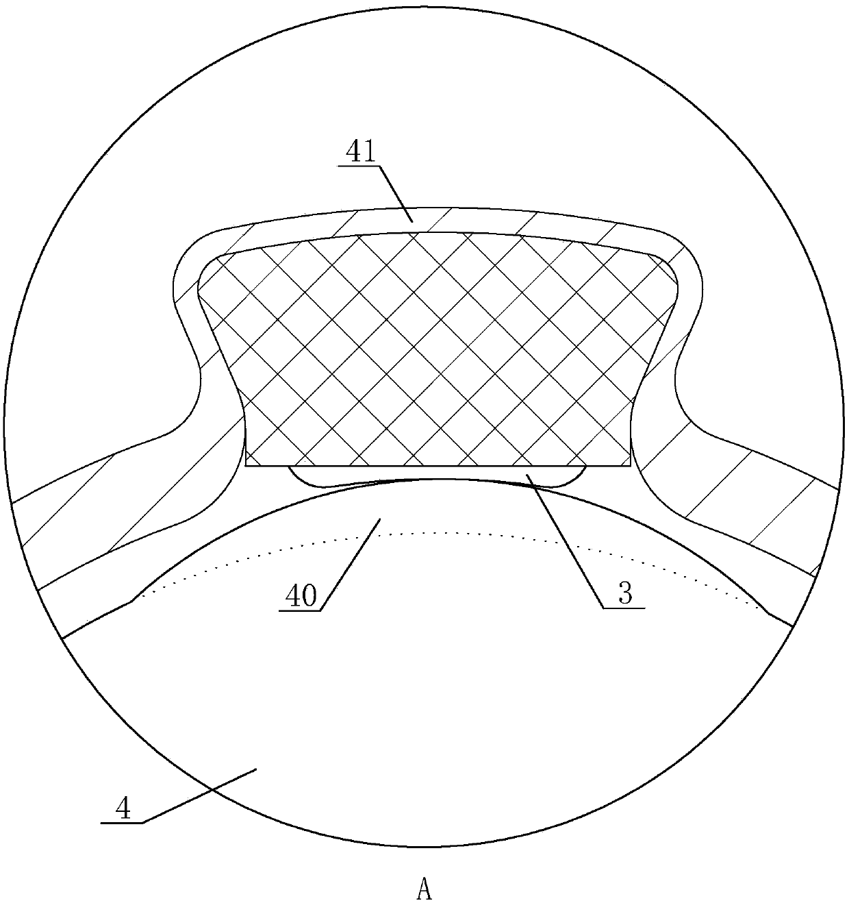
[0036] The side wall of the knob 4 is provided with a push bump 40 for rotating the push portion of the switch button 3 of the trigger switch assembly to expand and contract; the push bump 40 is spherical, and the push portion of the switch button 3 faces the push bump 40 A spherical groove is provided on one side of the cam, and the spherical groove is matched with the pushing projection 40 .

[0037]...

Embodiment 2

[0055] The difference between this embodiment and Embodiment 1 is that the second contact portion 110 is a metal ring with a slope, the slope of the metal ring faces the rear end of the movable contact 31 , the convex portion 310 is annular, and the movable contact 30 is truncated.

[0056] The corresponding effects are as follows: First, the annular inclined surface of the metal ring forms a tapered surface, and the second contact portion 110 can increase the contact area between the second contact portion 110 and the convex portion 310 , effectively avoiding the phenomenon of poor contact and improving safety.

[0057] Secondly, the conical surface of the metal ring is matched with the annular convex part 310, so that the convex part 310 and the metal ring can be concentric, ensuring the concentricity of the two, so that the top of the contact can be accurately aligned with the arc-shaped contact part of the first contact part 100 1001, to avoid poor contact caused by misalig...


PUM


Abstract

The invention provides a waterproof knob switch. The internal trigger switch assembly comprises a casing body, a switch button, an automatic isolation door structure and a main spring applied to the switch button. The switch button comprises a movable contact. A convex part is arranged on the rear end of the movable contact. The casing body is provided with a first accommodation cavity, a second accommodation cavity, a first wiring terminal and a second wiring terminal. The automatic isolation door structure comprises a wire control, a pulley block and an opening and closing door with a resetting mechanism. When the switch button is pressed, opening and closing of the opening and closing door are controlled through the wire control and the pulley block. When the opening and closing door is closed tightly under the action of the reset mechanism, the first wiring terminal inside the first accommodation cavity can be closed to prevent water vapor from entering the first accommodation cavity, so that the first wiring terminal and the second wiring terminal are completely disconnected. The waterproof knob switch is waterproof, is not easily damped and aged, and has high safety. The service life of the trigger switch assembly is improved. The safety and the waterproofness of the whole knob switch are improved.

Description

technical field [0001] The invention relates to a circuit control device, which is a waterproof knob switch. Background technique [0002] The switch is a device used to control the power on and off of the circuit, but since the switch is basically energized (that is, there is voltage on the live wire), when the switch is not in use, the circuit in the switch still has electricity, and when the liquid enters the switch When the voltage is still maintained on the live wire, the circuit in the switch will be short-circuited at the moment when the liquid enters, causing the electrical appliance or switch to burn out, and there is a high safety problem. [0003] At the same time, if the switch is in an environment with high water vapor for a long time, the water vapor will accelerate the aging and oxidation of the circuit in the switch, resulting in the failure of the switch control. [0004] Therefore, how to prevent liquid or water vapor from contacting the circuit in the swi...

Claims


Application Information

Patent Timeline
Patent Type & Authority Patents(China)
IPC IPC(8): H01H13/06H01H13/14H01H13/20
CPCH01H13/06H01H13/14H01H13/20
Inventor 纪孔金
Owner 台州小眼睛科技有限公司
Why Eureka
Try Eureka