
Rotating machine fault diagnosis method based on peak index

A technology of rotating machinery and peak index, which is applied in fault diagnosis of rotating machinery and the field of fault diagnosis of rotating machinery based on peak index. High reliability, not easy to misjudgment, good sensitivity

Active Publication Date: 2016-10-12
GUANGDONG UNIV OF PETROCHEMICAL TECH
View PDF3 Cites 1 Cited by
  • Summary
  • Abstract
  • Description
  • Claims
  • Application Information

AI Technical Summary

Problems solved by technology

[0007] However, the prior art using peak index diagnosis is a technical method that uses "peak parameters" for equipment fault diagnosis. The use of peak index to diagnose rotating machinery faults mainly has the following problems: First, the idea of ​​signal separation is not used Constructing a peak index does not separate the standard vibration signal, so it cannot better reflect the fault of the rotating machinery, and is not sensitive to fault diagnosis; second, the peak index is only reliable when the signal has obvious pulsation, and when the fault of the rotating machinery continues After the peak value gradually reaches the limit value, the root mean square value begins to increase, and the peak index gradually decreases until it returns to the size when there is no fault. Therefore, the peak index has failure to judge the fault, especially some weak fault signals. Sensitive, prone to misjudgments, the accuracy and reliability of fault diagnosis of rotating machinery is poor; third, the vibration signal of the running-in period is used as the standard vibration signal, without considering the serious noise in the vibration signal of rotating machinery equipment in the early stage of operation, which is not suitable as a Problems with standard vibration signals, inaccurate fault diagnosis

Method used


Image

  • Rotating machine fault diagnosis method based on peak index
  • Rotating machine fault diagnosis method based on peak index
  • Rotating machine fault diagnosis method based on peak index

Examples


Embodiment Construction

[0038] The following is a further description of the technical solution of a method for diagnosing faults of rotating machinery based on peak indicators provided by the present invention in conjunction with the accompanying drawings, so that those skilled in the art can better understand the present invention and implement it.

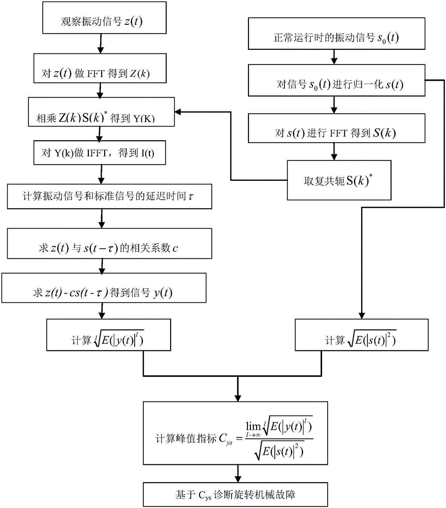
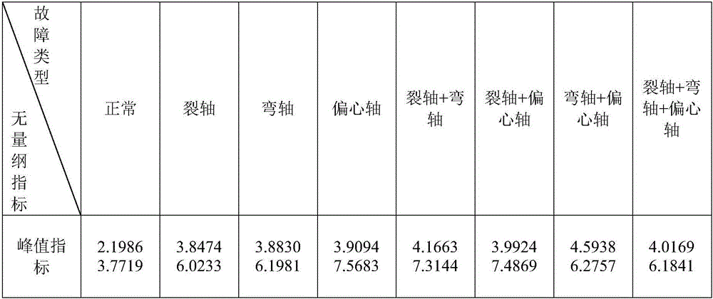
[0039] see figure 1 And table 1, the present invention provides a kind of rotating machinery fault diagnosis method based on peak index, comprises the following steps:

[0040] (1) Use the vibration acceleration sensor to collect the normal operating parameters of the rotating machinery after the running-in period, and the normal operating parameters are based on the sampling frequency f sAcquired fault-free vibration signal s 0 (t)(t=0,1,…,T-1), sampling is performed as a group of 1024 points, 50 groups of peak indicators are taken, and the minimum and maximum values ​​of the 50 groups of peak indicators are taken as the peak indicator range of valu...


PUM


Abstract

The invention provides a rotating machine fault diagnosis method based on a peak index. A peak index is constructed based on the idea of signal separation to overcome the shortcomings of the traditional peak index diagnosis technology and improve the accuracy and reliability of diagnosis. Based on a standard vibration signal, vibration signals acquired in real time are divided into trouble-free vibration signals and mixed signals. A peak index is constructed using mixed signals and trouble-free vibration signals, the peak index is more sensitive to fault diagnosis, and weak fault feature signals can be better detected through signal change. There is less overlap between the value range of peak index under normal operation of rotating mechanical equipment and the value range of peak index under failure of the rotating mechanical equipment, and the peak index changes apparently under different conditions. The peak index is sensitive to the fault of an eccentric shaft, and the fault can be well differentiated from other faults. Rotating machine fault diagnosis is highly precise and reliable.

Description

technical field [0001] The invention relates to a method for diagnosing a fault of a rotating machine, in particular to a method for diagnosing a fault of a rotating machine based on a peak index, and belongs to the technical field of fault diagnosis and signal processing and analysis. Background technique [0002] Large-scale rotating machinery equipment (such as steam turbines, rotating bearings, compressors, etc.) is the key equipment in important engineering fields such as petroleum, chemical industry, machinery manufacturing, and aerospace. Rotating machinery equipment is constantly developing in the direction of large-scale, automation, and precision , its composition and structure are becoming more and more complex, and the probability of failure is also increasing, so the requirements for the safety and reliability of large rotating machinery equipment are also getting higher and higher. [0003] However, when large-scale rotating machinery fails, vibration monitorin...

Claims


Application Information

Patent Timeline
IPC IPC(8): G01M13/02G01M13/04
CPCG01M13/028G01M13/045
Inventor 张清华王子为何俊谭巨兴肖明
Owner GUANGDONG UNIV OF PETROCHEMICAL TECH
Learn More